The hardware structure of the temperature control system consists of five parts: temperature measurement and A/D conversion circuit, signal test and processing circuit, keyboard scanning and display circuit, control output circuit and power supply circuit. The system block diagram is shown in the figure below.
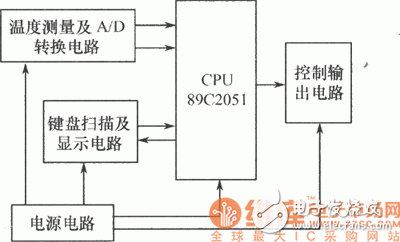
(1) Signal test and processing circuit: The core control part of the temperature controller adopts the high cost-effective 8-bit microcontroller AT89C2051 produced by AT, which is used to complete data measurement and processing, and realize the measurement and control of beverage temperature Features.
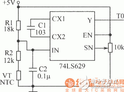
(2) Temperature measurement and A/D conversion circuit: The following figure shows the temperature measurement and A/D conversion circuit. The temperature measurement circuit is completed by a voltage divider circuit composed of a temperature sensor VT and R1 and R2, and the temperature sensor uses a negative temperature coefficient thermistor VT. The MD conversion circuit uses a voltage-controlled oscillator to realize the digital conversion of the analog quantity. The temperature sensing circuit provides the temperature sampling level for the voltage-controlled oscillator. Through VF conversion, the electrical signal representing the temperature is converted into a square wave signal, which is output by the 74LS629 To the T0 pin of the CPU. The CPU counts the square wave with the counter T0 within a given time and calculates the correct temperature.
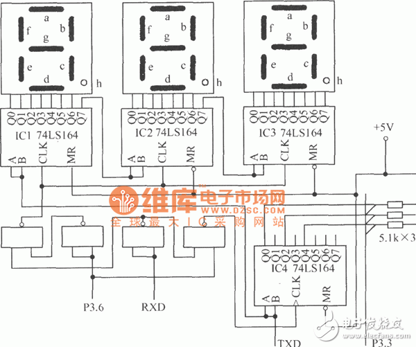
(3) Keyboard scanning and display circuit: The following figure shows the keyboard scanning and display circuit. This part of the circuit is composed of a serial communication port, P3.3 and P3.6 ports to expand a 3-digit LED display, and a 3-key keyboard. The expansion is completed by the 8-bit parallel serial shift register 74LS164.
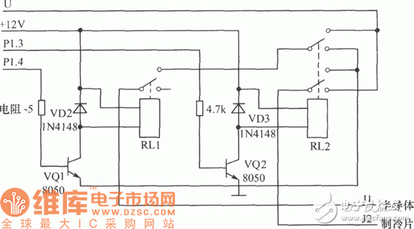
(4) Control output circuit: The figure below is the output control circuit for temperature adjustment. P1.3 drives the 12V/10A relay RL1 through VQ2 to control the working voltage of the semiconductor refrigeration film. P1.4 drives the 12V relay RL2 with normally open and normally closed double contacts through VQ1 to control and switch the polarity of the working voltage applied to the semiconductor refrigeration chip to realize heating and cooling.
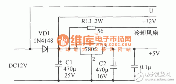
(5) Power supply circuit: The heating and cooling part of the temperature controller is realized by semiconductor refrigeration chips. In order to achieve rapid heating and cooling, the power supply is required to provide a 12V DC voltage with an output current of not less than 5A. The circuit is shown in the figure below. After 12V DC is isolated by VD1, one way is regulated by 7805 for CPU use; one way is supplied by R13 for cooling fan, and the other way is supplied by relay.
Software design: The MCS-51 assembly language programming program for the system is mainly composed of the following parts.
(1) Keyboard scan display program. The keyboard scan is interrupted by the T1 timer to scan the keyboard circuit regularly, working in the mode 1 state. The display part is driven by the serial port and works in mode 0 (shift register mode).
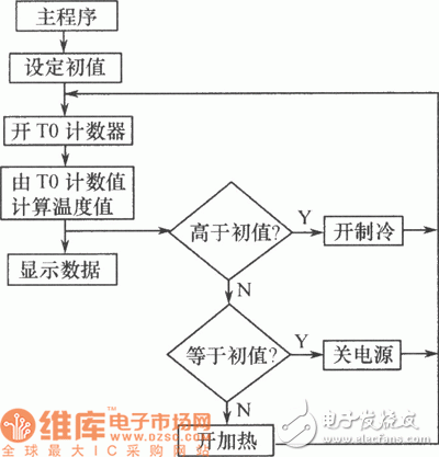
(2) Control output program. The CPU counts the square wave output by the 74LS629 with the timing pin counter T0 and calculates the correct temperature. According to the comparison between this temperature and the set temperature, it controls the output of the P1.3 and P1.4 ports and changes the work of the semiconductor refrigeration chip. Polarity to achieve heating and cooling.
(3) The main program. The main program block diagram is as follows
Communication Industrial Control Monitoring And Automation Connecting Line
Communication industrial control monitoring and automation connecting line:RJ11,RJ45,RF,M8,M12,Wire to Wire,DC JACK,Phone Jack,DISPLAYPORT CABLE,DIN
Industrial control harness: 1, according to customer requirements to provide different types of connector and enclosure suitable wire
2. Line color according to customer requirements
3. The joint meets the requirements of ipc-620
4. Assembling and testing equipment ensures correct wiring diagram and high efficiency of production line
5. 100% path short circuit test
6. 100% high voltage test
Industrial equipment harness
1: Application Industry: widely used in, instrumentation, automobile, machinery, electric vehicle, machine tool equipment, medical equipment, electronics, industrial automation, signal transmission, power control, and other high-tech electrical products.
2: It can be customized.
3: Product advantages: small batch can be done, processing equipment is perfect, testing equipment is perfect.
Communication industrial control monitoring and automation connecting line
ShenZhen Antenk Electronics Co,Ltd , https://www.antenksocket.com