The circuit in Figure 1 produces an output voltage that you can measure to determine if the two sine waves are in an orthogonal relationship. If the output voltage is 0V, the input waves (φ1 and φ2) are completely orthogonal. If there is a non-90° phase difference in the input, the circuit outputs a DC voltage. This voltage is proportional to the degree of non-orthogonality of the two input signals. When the phase angle is less than 90°, the voltage polarity is positive, and when the phase angle is greater than 90°, the voltage polarity is negative.
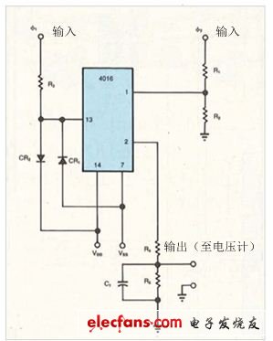
Figure 1 uses the bidirectional switch in the circuit to determine if the two sine waves are orthogonal. If the output voltage is 0V, the input waves (φ1 and φ2) are completely orthogonal. If the output voltage is positive or negative, the input wave is non-orthogonal.
Signal A and signal B in Figure 2 are orthogonal. When signal A is applied to the φ1 input, the bidirectional CMOS switch is turned on during the positive half cycle and turned off during the negative half cycle. If signal B is applied to the φ2 input at the same time, pin 2 has an output similar to signal C. It should be noted that the area above and below the ground line is equal. R5C1 in Figure 1 is an integration network, resulting in a network voltage drop of 0V.
If the phase angle is greater than 90° and the area above the local line is larger than the area below the ground, the output voltage is positive (D). If the phase angle is less than 90°, the output voltage is negative (E). If 4016 is triggered at a non-zero voltage, the accuracy of the detector will not change.
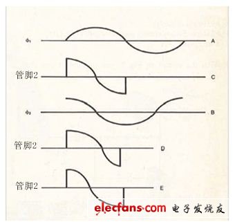
Figure 2 When φ1 and φ2 are orthogonal, the output of pin 2 (C) proves that the area above and below the ground is equal, so that the integrated output voltage at pin 2 is 0V. If the sine wave is non-orthogonal, the integrated output voltage is positive (D) or negative (E).
R3, D1, and D2 provide input protection for the integrated circuit. The performance of the R4/R5/C1 integrator depends on the frequency of the input signal and the network impedance at pin 1. If R1 is 8.2kΩ, R2 is 2.2kΩ, and R4, R5, and C1 are 8.2Ω, 4.7kΩ, and 3.2μF, respectively, the integrator has good performance at 25 kHz. These values ​​are suitable for a 24V pp swing on the φ2 input. The values ​​of VDD and VSS must be large enough to accommodate the 4016 input swing. For example, a ±3V input swing requires VDD to be 5V and VSS to be -5V.
FC/PC Fiber Optic Fast Connector
Fc/Pc Fiber Optic Fast Connector,Optical Fiber Fast Connector,Fast Sc Connector,Fast Connector Ftth
Ningbo Fengwei Communication Technology Co., Ltd , https://www.fengweifiberoptic.com