The function of the 555 timer is mainly determined by two comparators. The output voltages of the two comparators control the state of the RS flip-flops and discharge tubes. Apply a voltage between the power supply and ground. When the 5 pin is left floating, the voltage at the inverting input of the voltage comparator A1 is 2VCC /3, and the voltage at the non-inverting input of A2 is VCC /3. If the voltage at the trigger input terminal TR is less than VCC /3, the output of comparator A2 is 1, which sets the RS flip-flop to 1 and the output terminal OUT=1. If the voltage at the threshold input terminal TH is greater than 2VCC/3 and the voltage at the TR terminal is greater than VCC /3, the output of A1 is 1 and the output of A2 is 0. The RS flip-flop can be set to 0 to make the output 0 level.
The 555 timer has low cost and reliable performance. It only needs several external resistors and capacitors to realize pulse generation and conversion circuits such as multivibrator, monostable trigger and Schmitt trigger. It is also widely used as a timer in instrumentation, household appliances, electronic measurement and automatic control. The internal circuit block diagram and external pinout diagram of the 555 timer are shown in Figure 2.9.1 and Figure 2.9.2, respectively. It consists of two voltage comparators, three equivalent series resistors, an RS flip-flop, a discharge tube T and a power output stage. It provides two reference voltages VCC /3 and 2VCC /3
The function of the 555 timer is mainly determined by two comparators. The output voltages of the two comparators control the state of the RS flip-flops and discharge tubes. Apply a voltage between the power supply and ground. When the 5 pin is left floating, the voltage at the inverting input of the voltage comparator A1 is 2VCC /3, and the voltage at the non-inverting input of A2 is VCC /3. If the voltage at the trigger input terminal TR is less than VCC /3, the output of comparator A2 is 1, which sets the RS flip-flop to 1 and the output terminal OUT=1. If the voltage at the threshold input terminal TH is greater than 2VCC/3 and the voltage at the TR terminal is greater than VCC /3, the output of A1 is 1 and the output of A2 is 0. The RS flip-flop can be set to 0 to make the output 0 level.
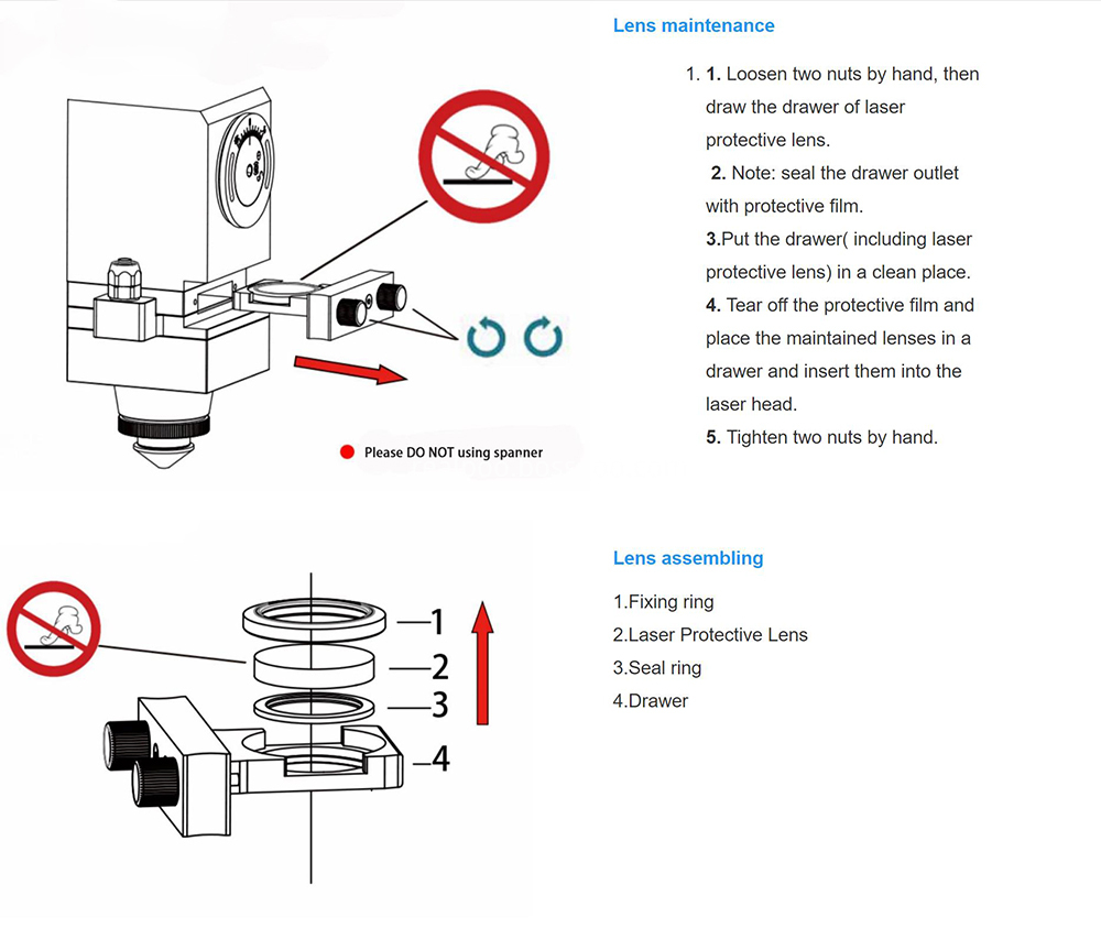
Realpoo Optics offer high quality fused silica laser protective windows are designed for useing with high power fiber lasers, to protective laser optics against damage from material splatter. Laser proteictive window is coated AR coating 1064nm in both sides. The substrate of the window is normally JGS1 or Fused Silica(FS). The diameter 18mm to 55mm is available.

Laser Protective Lens,Laser Cutting Fused Silica,Laser Fused Silica Glass, Laser Protective Window
Changchun Realpoo Photoelectric Co., Ltd. , https://www.optics-realpoo.com