Instrumentation amplifiers can condition the electrical signals generated by the sensors, so that digitizing, storing, or using them for control signals is typically small, so the amplifiers may need to be configured for high gain. In addition, the signal may superimpose a large common-mode voltage or may superimpose a large dc offset voltage. Precision instrumentation amplifiers provide high gain, selectively amplifying the difference between the two input voltages while suppressing the signals common to both inputs.
The Wheatstone bridge is a classic example of this situation, but galvanic cells like biosensors have similar characteristics. The bridge output signal is a differential signal, so the instrumentation amplifier is the first choice for high precision measurements. Ideally, the unloaded bridge output is zero, but this is true only if all four resistors are identical. If there is a bridge built with discrete resistors, as shown in Figure 1. Worst case differential offset VOS is
![]() (1)
(1)
Among them, VEX is the bridge excitation voltage, and TOL is the resistance tolerance (in percentage).
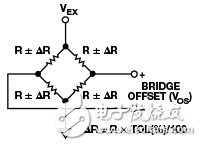
Figure 1 Wheatstone bridge imbalance
For example, when the tolerance of each component is 0.1% and the excitation voltage is 5 V, the differential offset can be as high as ±5 mV. If a gain of 400 is required to achieve the desired bridge sensitivity, the offset at the output of the amplifier becomes ±2 V. Assuming the amplifier is driven by the same power supply and its output can be rail-to-rail oscillating, only bridge offsets can consume more than 80% of the output swing. This problem will only get worse as the industry demands a smaller and smaller supply voltage.
The traditional three-op-amp instrumentation amplifier architecture (shown in Figure 2) has a differential gain stage followed by a subtractor that removes the common-mode voltage. The gain is applied to the first stage, so the multiple of the offset amplification is the same as the target signal. Therefore, the only way to remove it is to apply a counter voltage at the reference (REF) terminal. The main disadvantage of this method is that if the first stage of the amplifier is already saturated, adjusting the voltage on REF does not correct the offset. Several ways to overcome this deficiency include:
According to the specific situation, the bridge is shunted by an external resistor, but for automated production, this is unrealistic and cannot be adjusted after leaving the factory.
Reduce the first stage gain, remove the offset by trimming the voltage on REF, and add an additional amplifier circuit to achieve the desired gain
Reduce the first stage gain, complete the digital output with a high resolution ADC, and remove the offset in the software
The latter two options also need to take into account the worst-case deviation from the original offset value, further reducing the maximum gain of the first stage. These solutions are not ideal because they require additional power, board space, or cost to achieve high CMRR and low noise goals. In addition, AC coupling is not an option for measuring DC or ultra-slow motion signals.
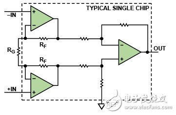
Figure 2 Three op amp instrumentation amplifier topology
Indirect Current Feedback (ICF) instrumentation amplifiers (such as the AD8237 and AD8420 can remove the offset before amplification. Figure 3 shows the ICF topology schematic.
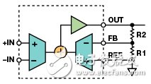
Figure 3 Indirect current feedback instrumentation amplifier topology
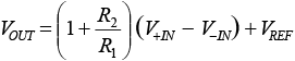
The transfer function of the instrumentation amplifier is identical in form to the transfer function of the classical three op amp topology, and its calculation formula is
 (2)
(2)
Since the voltage between the inputs is equal to the voltage between the feedback (FB) and reference (REF) terminals, the amplifier's feedback requirements can be satisfied, so we can rewrite the equation to
 (3)
(3)
This means that a voltage equal to the offset between the feedback and reference terminals is introduced, and the output can be adjusted to zero volts even in the presence of large input offsets. As shown in Figure 4, this adjustment can be achieved by injecting a small current into the feedback node via resistor RA from a simple voltage source (such as a low cost DAC) or a filtered PWM signal from an embedded microcontroller.
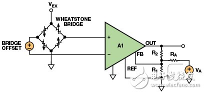
Figure 4 High gain bridge circuit with offset removal
Yacenter hook-up wire and lead wire is manufactured to strict industry specifications. Our collection of hook-up wire and lead wire may be applied for electronic use where high temperatures are encountered. PTFE Coated hook-up wire possesses excellent resistance to thermal aging, solder iron damage, flame, and moisture. Allied Wire offers electrical wire in a range of insulating materials, colors and sizes. Insulating materials include PVC, Irradiated PVC, Irradiated Polyolefin and PTFE. AWC hook-up wire products efficiently answer marketplace demands.
Lead Wire,Balloon Detonator Wire,Ph Connector Harness,Fan Wiring Harness
Dongguan YAC Electric Co,. LTD. , https://www.yacentercns.com