A tri-state gate is a gate that has three states (0, 1, high resistance). A transmission gate is a gate that can control the opening and closing of a path. When it is turned on, one end signal can be transmitted to the other end. When it is not conductive, one end signal cannot be transmitted to the other end. The two are not reciprocal relations. The three-state gates in digital circuits can have various implementation methods. One of them is the use of transmission gates.
Note: The high-impedance state (Z-state) refers to the output states of the two output TTL pins of the gate that drive TTL or MOS transistors (ie, the pull-up network and the pull-down network) are in the off state.
Three-state doorThree-state gates are an important bus interface circuit.
Three-state means that its output can be either a normal binary logic circuit, ie, a normal high level (logic 1) or a low level (logic 0), while maintaining a unique high impedance state. The high-impedance state is equivalent to the blocking state (high resistance, equivalent to an open circuit).
Three-state gate structure High-impedance state is a common term in a digital circuit, referring to an output state of the circuit, neither high nor low, if the high-impedance state and then enter the next circuit, The lower circuit has no effect, and if it is not connected, if it is measured with a multimeter, it may be high level or it may be low level, which is followed by what is connected to it.
In the high-impedance state, the output resistance is large, equivalent to an open circuit, without any logic control function. The significance of a high-impedance state is that it is not possible to break the circuit in an actual circuit. The control of the output logic state of the tri-state circuit is implemented by an input pin.
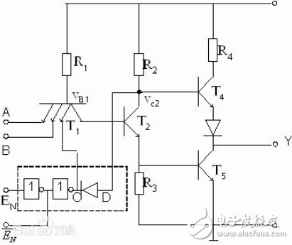
The tri-state gate has an EN control enable terminal to control the on-off of the gate circuit. Devices that can have these three states are called three-state devices. When EN is active, the tri-state circuit exhibits a normal "0" or "1" output; when EN is inactive, the tri-state circuit gives a high-impedance output.
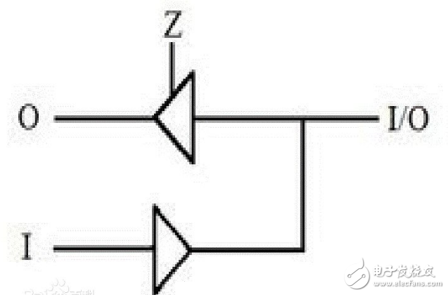
When the tri-state gate is used in the bidirectional port, as shown in Fig. 1, Z is set as a control term. When Z=1, the tri-state gate is in a high-impedance state, and the upper line cannot be input only. When Z=0, The tri-state gate has a normal high-level and low-level output state that can be output, that is, an O-way pass. The tri-state gate is an output stage that extends the logic function and is also a control switch. Mainly for the bus connection, because the bus allows only one user at a time. There are usually multiple devices connected to the data bus, each of which is strobed by a signal such as OE/CE. If the device is not strobed, it is in a high-impedance state, which means that it is not connected to the bus and does not affect the operation of other devices.
Tristate refers to: high level, low level, and high impedance.
Three-state gates have three output states: output high, output low, and high-impedance. The first two states are working states, and the latter state is prohibited. It is worth noting that the tri-state gate does not have three logical values. In the working state, the output of the tri-state gate can be a logic '0' or a logic '1'; in the disabled state, the output exhibits a high-impedance state, which is equivalent to an open circuit.
Tri-state gates have a wide range of applications. Lines can be implemented using tri-state gates and are also widely used in bus transfers. When the bus is transmitted, in order to ensure the accuracy of data transmission, at any time, only one control terminal of n tri-state gates can be 1, and the others are 0. The use of high-resistance states for tri-state gates can achieve this well. characteristic.
Transmission gateThe CMOS transmission gate (TransmissionGate) is a controllable switching circuit that can transmit both digital signals and analog signals. The CMOS transmission gate consists of a PMOS and an NMOS transistor in parallel, which has a very low on-resistance (several hundred ohms) and a very high off-resistance (greater than 10^9 ohms).
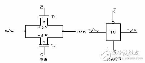
The so-called transmission gate (TG) is an analog switch that transmits analog signals. The CMOS transfer gate consists of a P-channel and an N-channel enhancement MOSFET in parallel as shown in the figure below.
How cmos transmission gates work
TP and TN are symmetrical devices whose drain and source are interchangeable. Let their turn-on voltage |VT|=2V and the input analog signal change from -5V to +5V. In order to make the PN junction between the substrate and the drain source not to be positively biased at any time, the substrate of the TP is connected to the +5V voltage, and the substrate of the TN is connected to the -5V voltage. The gates of the two tubes are controlled by complementary signal voltages (+5V and -5V) using C and! C said.
The operating conditions of the transmission gate are as follows: When C is connected to a low voltage of -5V, the gate voltage of TN is -5V, and when VT takes any value within the range of -5V to +5V, TN does not conduct. At the same time, the gate voltage of TP is +5V, and TP does not conduct. It can be seen that when C is connected to a low voltage, the switch is open. To enable the switch, C can be connected to a high voltage +5V. At this time, the gate voltage of TN is +5V, vI is in the range of -5V to +3V, and TN is turned on. At the same time, the TP voltage of the TP is -5V, and the TP will be turned on within the range of -3V to +5V.
From the above analysis, we can see that when ν "-3V, only TN conduction, and when vI" +3V, only TP conduction when vI in the range of -3V to +3V, TN and TP are two guides through.
Further analysis can also see that the deeper one tube is conducting, the less conductive the other tube is. In other words, when the on-resistance of one tube decreases, the on-resistance of the other tube increases. Since the two tubes are operated in parallel, the on-resistance of the switch can be approximately considered as a constant. This is the advantage of CMOS transfer out. In normal operation, the on-resistance of an analog switch is approximately a few hundred ohms. When it is connected in series with a megohm amplifier with an input impedance, it can be neglected.
Logical function
The output characteristics of MOSFETs are linearly symmetrical near the origin, so they are often used as analog switches. Analog switches are widely used for sampling - hold circuits, chopper circuits, analog-to-digital and digital-to-analog converter circuits. In the digital logic circuit design, the left end of the transmission gate is input, and the right end is the output. The upper end C is opposite and the lower end is the control end. When C is 0 and C is 1, the TG gate is opened. At this time, the right end output out=left input in .
Transmission gate application
(1) Gated oscillator
As shown in FIG. 3, when c is "1", the TG conduction circuit oscillates and VO outputs a square wave; when c is "O", TG is turned off and the circuit stops oscillating.
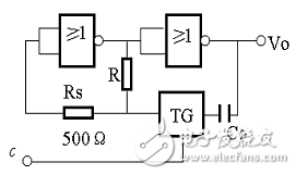
Figure 3 gated oscillator
(2) Programmable pulse oscillator
If you want to obtain different frequency square wave can be used as shown in Figure 4, as long as the A, B, C by adding different levels of control, you can get a rectangular wave of different frequencies.
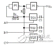
Figure 4 programmable pulse oscillator
(3) Programmable operational amplifier
The transmission gate can transmit digital signals, and can also transmit analog signals. The feedback part of the operational amplifier adopts program control, which can change the amplifier's voltage amplification. Figure 5 programmable amplifier
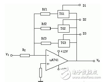
Figure 5 program-controlled amplifier
A manual pulse generator (MPG) is a device normally associated with computer numerically controlled machinery or other devices involved in positioning. It usually consists of a rotating knob that generates electrical pulses that are sent to an equipment controller. The controller will then move the piece of equipment a predetermined distance for each pulse.
The CNC handheld controller MPG Pendant with x1, x10, x100 selectable. It is equipped with our popular machined MPG unit, 4,5,6 axis and scale selector, emergency stop and reset button.
Manual Pulse Generator,Handwheel MPG CNC,Electric Pulse Generator,Signal Pulse Generator
Jilin Lander Intelligent Technology Co., Ltd , https://www.jilinlandermotor.com