The article details the DU8608 chip based on non-isolated BUCK topology, source drive MOSFET, to achieve extremely high precision LED constant current control. The test proves that the full-closed TRUEC2 technology detects the real output current in real time, and is immune to the input voltage and external inductance, which has improved the accuracy of the LED output current.
I. Introduction
For the characteristics of LED lighting load, the topology of the current non-isolated constant current driving power supply is basically a BUCK step-down structure. The mainstream scheme is to fix the peak current by fixing the off time to achieve a fixed output current control strategy. This paper will discuss the principle of this control strategy to achieve constant current, analyze the advantages and disadvantages of this open-loop control strategy, and the peripheral compensation required to apply this control strategy. At the same time, based on the DU8608 chip, introduce this new closed-loop current control strategy. In detail, how this control strategy can improve the accuracy of LED output current breakthrough, from the open loop to the closed loop is its essential breakthrough.
Second, principle and design
2.1 Current mainstream control strategy for LED non-isolated constant current drive current
As shown in Figure 1, the circuit is a BUCK buck structure, and the chip controls the source of the MOSFET. This is an open-loop constant current control method. The control principle is as follows:
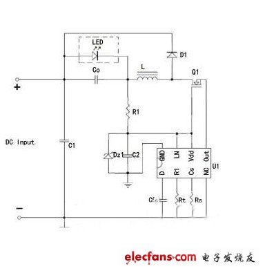
When the MOSFET is turned on, current flows from the DCBUS through the LED load, through the inductor, and into the ground.
Vi-Vo=Ldi/dt=L*Ir/DT (1)
When the MOSFET is turned off, the inductor current continues to flow from D1. The following formula is obtained:
Vo=Ldi/dt=L*Ir/(1-D)T (2)
Io(average)=Ipk-1/2*Ir (3)
From (2) and (3) Io=Vref/Rs-Vo*(1-D)T/(2*L) (4)
Both Vref and Rcs are set values. Since the current flows through the LED load, if the current is fixed, the voltage Vo of the LED can be considered to be fixed. Therefore, as shown in equation (4), as long as the inductance value L is fixed, the fixed value is fixed. Break time (1-D)T, Io is fixed.
Therefore, this open-loop control strategy is that the resistor connected to Rt sets the turn-off time of the MOSFET. At the beginning of each cycle, the MOSFET turns on until the inductor current rises to the peak value of Vref/Rs, at which point the MOSFET is turned off and the turn-off time is determined by Rt. After the set off time, the MOSFET is turned back on, so that it works repeatedly. The off time controls the average current of the ripple current LED. According to the current value to be output, the Rs value of the CS pin is adjusted, the Rt value is adjusted, and the off time of each switching cycle is fixed to a value, thereby realizing the output current. Constant current.
This is a simple and effective control strategy, but since this is an open-loop control mode, it can only detect the peak current on the inductor and cannot detect the output current. The output current accuracy is prone to deviation in three cases:
1. Input voltage fluctuations. (Open loop control, unable to feedback, system delay)
2. Mass production of inductance inductance deviation. (In Equation 4, the L change causes the Io to change)
3. LED load voltage is not the same (Vo).
Fiber Optic Ip68 Enclosure,Ftta Ip68 Hardened Connections Device,Ftta Ip68 Hardened Connections Fast,Fiber Optic Ip68 Enclosure Adapter
Huizhou Fibercan Industrial Co.Ltd , https://www.fibercannetworks.com