Abstract: The design of cellular transmitters depends on high-performance RF modulators that maintain high linearity and high dynamic range. With the growth of multi-carrier transmitters, RF modulators must maintain a low-noise floor to provide higher performance indicators, which usually depend on second- or third-order intermodulation. This article discusses these requirements and shows that the MAX2022 can meet the requirements of a typical four-carrier WCDMA transmission architecture.
Overview Most existing cellular base stations use a superheterodyne structure to send or receive radio frequency signals. This structure requires two frequency conversions or more up and down conversion stages, intermediate filtering and analog signal processing. The upper part of Figure 1 shows a typical superheterodyne transmission block diagram of a two-stage conversion cellular base station. Many such transmitters have been used in single carrier systems. Because the multi-carrier transmitter is copied from the single-carrier transmitter, more system hardware is introduced. In an effort to reduce the cost of the transmitter, many system designers have turned to multi-carrier transmitters and simple direct conversion RF structures.

Figure 1. Block diagram of superheterodyne transform and direct transform. Design challenge of multi-carrier structure. Multi-carrier structure reduces the number of transmit channels. The direct-transform structure directly transforms baseband signals into RF signals, thereby reducing the number of components per channel. Both of these structures require components with a wide dynamic range and high linearity to meet the requirements of the entire system. Figure 2 shows a direct conversion transmitter structure. This special structure greatly reduces the number of conversion processes. Multi-level mixers, amplifiers, intermediate frequency and RF filtering are replaced by a single-chip integrated solution.

Figure 2. Direct transformation structure
Until recently, the performance of digital-to-analog converters (DACs) and direct conversion modulators was insufficient to support the requirements of 3G multi-carrier cellular base stations. The transmitter design of the new generation of communication base stations requires both low cost and more flexible solutions. In the process of building the basic transmission architecture, the choice of RF modulator plays an important role. Solve the above problems with a single transmitter structure Maxim recently introduced a MAX2022 direct quadrature RF modulator that can meet these needs. This device provides a very wide dynamic range, which provides great support for transmitter designers in optimizing the performance of the entire system.
It has very high OIP2 and OIP3, and with an output noise floor close to -174dBm / Hz, it can ensure true multi-carrier performance. A single transmitter architecture can support multiple types of modulation, from CDMA2000, WCDMA to OFDM, and supports up to 9 carriers. Taking full advantage of these modulation capabilities in the transmitter design can effectively reduce the hardware requirements of the system, thereby reducing costs and increasing link flexibility.
The MAX2022 uses a silicon-germanium process that covers the frequency range of 1500MHz to 2500MHz. Figure 3 shows the internal structure of the circuit.
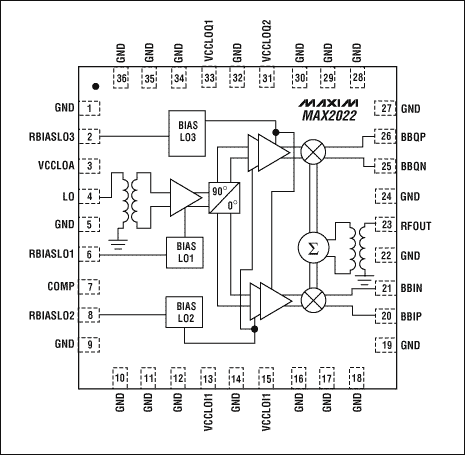
Figure 3. MAX2022 RF modulator performance
The MAX2022 has an internal 50Ω matched single-ended LO input, allowing the input drive range of the LO to be -3dBm to + 3dBm. After being internally buffered, the local oscillator is divided into two parts by a quadrature splitter and sent to two passive mixers. The I and Q quadrature inputs are differential inputs with 44Ω input impedance. An input bandwidth greater than 1GHz allows this chip to be used either as a baseband modulator directly to the radio frequency, or as a mirror suppression mixer with quadrature IF input. The quadrature input can be directly interfaced with the current output DAC, eliminating the intermediate buffer amplifier. The intermediate stage buffer amplifier in the traditional scheme not only limits the performance but also increases the cost. The mixer mixes the signal and sends it to the internal 50Ω matched single-ended RF output. MAX2022 RF Modulator Performance The performance of the RF modulator is determined by several independent parameters. The MAX2022 has excellent performance in all relevant fields. When P1dB is + 12dBm, OIP3 is + 22dBm. Intermodulation between multiple carriers depends on OIP3. A higher OIP3 can ensure lower intermodulation distortion. OIP2 is another important parameter for zero-IF applications. The OIP2 of the MAX2022 in the UMTS band is +50 dBm. OIP2 is of great significance to the baseband signal. The second harmonic of the baseband signal will produce a spectrum spread at the RF output, thereby compromising ACLR performance. Higher OIP2 can ensure lower ACLR distortion. Figure 4 shows the test results of OIP2 and OIP3 of this chip, and the output power in the frequency range of 1500MHz to 2500MHz.
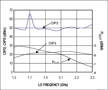
Figure 4. Correspondence between MAX2022 OIP2, OIP3, POUT and frequency
Compared with passive mixers, the noise floor of the MAX2022 has been greatly improved. The noise level of these devices is close to -174dBm / Hz at typical output signal amplitude. The phase noise of the local oscillator buffer will affect signals greater than -10dBm. However, the ultra-low phase noise design of the buffer -164dBc / Hz can guarantee the performance of the system.
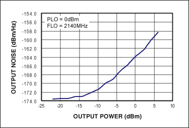
Figure 5. Noise floor and output power
Another key indicator of the RF modulator is the dynamic range, defined as the difference between the maximum effective signal level (expressed as P1dB) and the noise floor. The MAX2022 has a dynamic range of 186dB, far exceeding other integrated RF modulators.
In the PCS and UMTS bands, the local oscillator leakage is less than -40dBm, and the sideband suppression is better than 45dB. The digital pre-calibration control loop can further optimize the performance, making the local oscillator leakage less than -80dBm and the sideband suppression better than 60dB. The flatness of the RF passband is better than 0.5dB in the 100MHz bandwidth, which is very suitable for broadband systems. The advantages of multi-carrier WCDMA performance indicators working in the UMTS band are the intermodulation characteristics of multi-carrier. As can be seen from this article, the MAX2022 can provide outstanding performance.
As an example, we consider a 4-carrier WCDMA modulated signal, the transmitter design must meet the bandwidth requirements of the WCDMA carrier itself, equal to 20MHz. In addition, in order to correct the subsequent distortion caused by the power amplifier, it is necessary to add digital pre-distortion to the transmitted signal, so that the bandwidth requirement may exceed 100MHz. Figure 6 shows the spectrum of this signal.
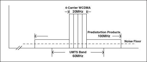
Figure 6. 4 carrier UMTS spectrum
It can be seen from the figure that the ultra-wideband makes the output spectrum of the transmitter exceed the bandwidth limit of UMTS. This requires that the noise specifications of the transmitter must meet the requirements of the transmitter template, beyond the edge of the frequency band, but does not require RF filters to handle spurious signals and noise levels. This puts high requirements on the RF modulator. The wide frequency band and large dynamic range of the MAX2022 can support such a system design.
Figure 7 shows the ACLR performance of single-carrier, dual-carrier, and 4-carrier WCDMA generated in the UMTS band. Based on the ultra-wide dynamic range, the MAX2022 can maintain a good ACLR in a very wide output power range. The figure also provides noise performance to illustrate the dynamic range that can be provided under the specified ACLR specifications. For example, for a 4-carrier WCDMA signal of -28dBm / carrier, ACLR can reach 66dB, and the output noise floor is -173.5dBm / Hz.
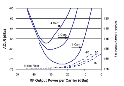
Figure 7. ACLR and noise performance of 1, 2 or 4 carrier WCDMA signals
The good performance of MAX2022 can also be used to generate other types of modulation, such as OFDM, QAM, etc. It can support up to 9 carriers in CDMA2000 and TD-SCDMA systems. A series of hardware configurations can implement any modulation method. System-level design The highly integrated interface design of the MAX2022 makes it very few requirements for peripheral auxiliary circuits, reducing system cost. The internally matched LO buffer and balun design allows the use of single-ended LO interfaces at low LO power levels of -3dBm to + 3dBm. The integrated RF balun allows single-ended RF output with 50Ω impedance matching. The I and Q component inputs of the baseband signal use a differential input interface with 44Ω internal impedance matching. These characteristics allow the chip to be directly connected to a high-performance current output DAC without the need for an intermediate buffer amplifier. According to the performance indicators of MAX2022, it is difficult to find an external baseband amplifier that does not degrade the performance of the device itself. Fortunately, in the MAX2022 application configuration, these baseband amplifiers are not necessary. Figure 8 provides a recommended circuit for DAC and MAX2022 terminal interface. A 50Ω to ground resistance provides proper DAC termination, and a peak current of 20mA typical corresponds to a baseband input of 0dBm.
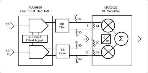
Figure 8. DAC and baseband input interface
To ensure the performance of the MAX2022, careful system-level design must be performed. Figure 9 is a recommended configuration with 4-carrier WCDMA modulation with digital predistortion capability. The figure shows the output signal level, noise level, and ACLR of each stage of the circuit.
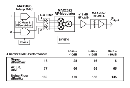
Figure 9. Tx signal analysis
Starting from the DAC, we require a device that can produce a 50MHz bandwidth, and ACLR is far better than the target value of 65dB for this design, while the noise and spurious levels are relatively low. MAX5895 is a device that can meet these requirements. The key DAC specifications are ACLR under 4 carrier operation, as well as noise and spurious levels. Interpolated DACs are recommended for this application. These DACs can operate at higher output sampling rates at relatively low input data rates. At this time, the attenuation of the interpolation filter is critical, because the subsequent low-pass filter of the DAC does not have sufficient attenuation of the adjacent interpolation image frequency component. The interpolated DAC generates the image frequency component at an integer multiple of the baseband input data rate. If these components are not eliminated at the input stage of the modulator, the image frequency components will produce severe sidebands at the output of the modulator. The MAX5895 95dB interpolated image rejection is ideal for this type of application. This fundamentally reduces the complexity of the DAC subsequent filters.
As can be seen from the modulator output, the modulator output signal level is -28dBm per carrier, for a total of -22dBm. The modulator performance determines ACLR to be + 66dB (the DAC specification has no limit). However, the noise floor has increased from -174dBm / Hz of the modulator to -170dBm / Hz. This is caused by the cascaded DAC noise level. Therefore, in order to get the optimal design, each unit in the circuit must be carefully selected.
The RF amplifier needs to have a very low noise figure and appropriate OIP3 to avoid degradation of the cascade ACLR. If the gain is 12dB, this level of OIP3 is preferably greater than + 30dBm. Selecting a high OIP3 output stage can avoid the degradation of the cascade ACLR. You can choose the MAX2057 RF adjustable gain amplifier, which can adjust the gain of the entire loop. + 37dBm OIP3 ensures that the cascade ACLR remains at + 65dB.
When each carrier maintains a noise floor of -139dBc / Hz, the transmitter should be able to generate ACLR of + 65dB. Such noise floor and spur levels are obtained without RF filters. The same hardware configuration can be used in a multi-band system without any changes. Conclusion The new modulator MAX2022 enables the transmission equipment to reach a new level. It can constitute zero intermediate frequency and image frequency suppression scheme. Using this device can easily improve system specifications, reduce costs, implement a flexible transmitter architecture, and help designers improve transmitter design efficiency.
Overview Most existing cellular base stations use a superheterodyne structure to send or receive radio frequency signals. This structure requires two frequency conversions or more up and down conversion stages, intermediate filtering and analog signal processing. The upper part of Figure 1 shows a typical superheterodyne transmission block diagram of a two-stage conversion cellular base station. Many such transmitters have been used in single carrier systems. Because the multi-carrier transmitter is copied from the single-carrier transmitter, more system hardware is introduced. In an effort to reduce the cost of the transmitter, many system designers have turned to multi-carrier transmitters and simple direct conversion RF structures.

Figure 1. Block diagram of superheterodyne transform and direct transform. Design challenge of multi-carrier structure. Multi-carrier structure reduces the number of transmit channels. The direct-transform structure directly transforms baseband signals into RF signals, thereby reducing the number of components per channel. Both of these structures require components with a wide dynamic range and high linearity to meet the requirements of the entire system. Figure 2 shows a direct conversion transmitter structure. This special structure greatly reduces the number of conversion processes. Multi-level mixers, amplifiers, intermediate frequency and RF filtering are replaced by a single-chip integrated solution.

Figure 2. Direct transformation structure
Until recently, the performance of digital-to-analog converters (DACs) and direct conversion modulators was insufficient to support the requirements of 3G multi-carrier cellular base stations. The transmitter design of the new generation of communication base stations requires both low cost and more flexible solutions. In the process of building the basic transmission architecture, the choice of RF modulator plays an important role. Solve the above problems with a single transmitter structure Maxim recently introduced a MAX2022 direct quadrature RF modulator that can meet these needs. This device provides a very wide dynamic range, which provides great support for transmitter designers in optimizing the performance of the entire system.
It has very high OIP2 and OIP3, and with an output noise floor close to -174dBm / Hz, it can ensure true multi-carrier performance. A single transmitter architecture can support multiple types of modulation, from CDMA2000, WCDMA to OFDM, and supports up to 9 carriers. Taking full advantage of these modulation capabilities in the transmitter design can effectively reduce the hardware requirements of the system, thereby reducing costs and increasing link flexibility.
The MAX2022 uses a silicon-germanium process that covers the frequency range of 1500MHz to 2500MHz. Figure 3 shows the internal structure of the circuit.

Figure 3. MAX2022 RF modulator performance
The MAX2022 has an internal 50Ω matched single-ended LO input, allowing the input drive range of the LO to be -3dBm to + 3dBm. After being internally buffered, the local oscillator is divided into two parts by a quadrature splitter and sent to two passive mixers. The I and Q quadrature inputs are differential inputs with 44Ω input impedance. An input bandwidth greater than 1GHz allows this chip to be used either as a baseband modulator directly to the radio frequency, or as a mirror suppression mixer with quadrature IF input. The quadrature input can be directly interfaced with the current output DAC, eliminating the intermediate buffer amplifier. The intermediate stage buffer amplifier in the traditional scheme not only limits the performance but also increases the cost. The mixer mixes the signal and sends it to the internal 50Ω matched single-ended RF output. MAX2022 RF Modulator Performance The performance of the RF modulator is determined by several independent parameters. The MAX2022 has excellent performance in all relevant fields. When P1dB is + 12dBm, OIP3 is + 22dBm. Intermodulation between multiple carriers depends on OIP3. A higher OIP3 can ensure lower intermodulation distortion. OIP2 is another important parameter for zero-IF applications. The OIP2 of the MAX2022 in the UMTS band is +50 dBm. OIP2 is of great significance to the baseband signal. The second harmonic of the baseband signal will produce a spectrum spread at the RF output, thereby compromising ACLR performance. Higher OIP2 can ensure lower ACLR distortion. Figure 4 shows the test results of OIP2 and OIP3 of this chip, and the output power in the frequency range of 1500MHz to 2500MHz.

Figure 4. Correspondence between MAX2022 OIP2, OIP3, POUT and frequency
Compared with passive mixers, the noise floor of the MAX2022 has been greatly improved. The noise level of these devices is close to -174dBm / Hz at typical output signal amplitude. The phase noise of the local oscillator buffer will affect signals greater than -10dBm. However, the ultra-low phase noise design of the buffer -164dBc / Hz can guarantee the performance of the system.

Figure 5. Noise floor and output power
Another key indicator of the RF modulator is the dynamic range, defined as the difference between the maximum effective signal level (expressed as P1dB) and the noise floor. The MAX2022 has a dynamic range of 186dB, far exceeding other integrated RF modulators.
In the PCS and UMTS bands, the local oscillator leakage is less than -40dBm, and the sideband suppression is better than 45dB. The digital pre-calibration control loop can further optimize the performance, making the local oscillator leakage less than -80dBm and the sideband suppression better than 60dB. The flatness of the RF passband is better than 0.5dB in the 100MHz bandwidth, which is very suitable for broadband systems. The advantages of multi-carrier WCDMA performance indicators working in the UMTS band are the intermodulation characteristics of multi-carrier. As can be seen from this article, the MAX2022 can provide outstanding performance.
As an example, we consider a 4-carrier WCDMA modulated signal, the transmitter design must meet the bandwidth requirements of the WCDMA carrier itself, equal to 20MHz. In addition, in order to correct the subsequent distortion caused by the power amplifier, it is necessary to add digital pre-distortion to the transmitted signal, so that the bandwidth requirement may exceed 100MHz. Figure 6 shows the spectrum of this signal.

Figure 6. 4 carrier UMTS spectrum
It can be seen from the figure that the ultra-wideband makes the output spectrum of the transmitter exceed the bandwidth limit of UMTS. This requires that the noise specifications of the transmitter must meet the requirements of the transmitter template, beyond the edge of the frequency band, but does not require RF filters to handle spurious signals and noise levels. This puts high requirements on the RF modulator. The wide frequency band and large dynamic range of the MAX2022 can support such a system design.
Figure 7 shows the ACLR performance of single-carrier, dual-carrier, and 4-carrier WCDMA generated in the UMTS band. Based on the ultra-wide dynamic range, the MAX2022 can maintain a good ACLR in a very wide output power range. The figure also provides noise performance to illustrate the dynamic range that can be provided under the specified ACLR specifications. For example, for a 4-carrier WCDMA signal of -28dBm / carrier, ACLR can reach 66dB, and the output noise floor is -173.5dBm / Hz.

Figure 7. ACLR and noise performance of 1, 2 or 4 carrier WCDMA signals
The good performance of MAX2022 can also be used to generate other types of modulation, such as OFDM, QAM, etc. It can support up to 9 carriers in CDMA2000 and TD-SCDMA systems. A series of hardware configurations can implement any modulation method. System-level design The highly integrated interface design of the MAX2022 makes it very few requirements for peripheral auxiliary circuits, reducing system cost. The internally matched LO buffer and balun design allows the use of single-ended LO interfaces at low LO power levels of -3dBm to + 3dBm. The integrated RF balun allows single-ended RF output with 50Ω impedance matching. The I and Q component inputs of the baseband signal use a differential input interface with 44Ω internal impedance matching. These characteristics allow the chip to be directly connected to a high-performance current output DAC without the need for an intermediate buffer amplifier. According to the performance indicators of MAX2022, it is difficult to find an external baseband amplifier that does not degrade the performance of the device itself. Fortunately, in the MAX2022 application configuration, these baseband amplifiers are not necessary. Figure 8 provides a recommended circuit for DAC and MAX2022 terminal interface. A 50Ω to ground resistance provides proper DAC termination, and a peak current of 20mA typical corresponds to a baseband input of 0dBm.

Figure 8. DAC and baseband input interface
To ensure the performance of the MAX2022, careful system-level design must be performed. Figure 9 is a recommended configuration with 4-carrier WCDMA modulation with digital predistortion capability. The figure shows the output signal level, noise level, and ACLR of each stage of the circuit.

Figure 9. Tx signal analysis
Starting from the DAC, we require a device that can produce a 50MHz bandwidth, and ACLR is far better than the target value of 65dB for this design, while the noise and spurious levels are relatively low. MAX5895 is a device that can meet these requirements. The key DAC specifications are ACLR under 4 carrier operation, as well as noise and spurious levels. Interpolated DACs are recommended for this application. These DACs can operate at higher output sampling rates at relatively low input data rates. At this time, the attenuation of the interpolation filter is critical, because the subsequent low-pass filter of the DAC does not have sufficient attenuation of the adjacent interpolation image frequency component. The interpolated DAC generates the image frequency component at an integer multiple of the baseband input data rate. If these components are not eliminated at the input stage of the modulator, the image frequency components will produce severe sidebands at the output of the modulator. The MAX5895 95dB interpolated image rejection is ideal for this type of application. This fundamentally reduces the complexity of the DAC subsequent filters.
As can be seen from the modulator output, the modulator output signal level is -28dBm per carrier, for a total of -22dBm. The modulator performance determines ACLR to be + 66dB (the DAC specification has no limit). However, the noise floor has increased from -174dBm / Hz of the modulator to -170dBm / Hz. This is caused by the cascaded DAC noise level. Therefore, in order to get the optimal design, each unit in the circuit must be carefully selected.
The RF amplifier needs to have a very low noise figure and appropriate OIP3 to avoid degradation of the cascade ACLR. If the gain is 12dB, this level of OIP3 is preferably greater than + 30dBm. Selecting a high OIP3 output stage can avoid the degradation of the cascade ACLR. You can choose the MAX2057 RF adjustable gain amplifier, which can adjust the gain of the entire loop. + 37dBm OIP3 ensures that the cascade ACLR remains at + 65dB.
When each carrier maintains a noise floor of -139dBc / Hz, the transmitter should be able to generate ACLR of + 65dB. Such noise floor and spur levels are obtained without RF filters. The same hardware configuration can be used in a multi-band system without any changes. Conclusion The new modulator MAX2022 enables the transmission equipment to reach a new level. It can constitute zero intermediate frequency and image frequency suppression scheme. Using this device can easily improve system specifications, reduce costs, implement a flexible transmitter architecture, and help designers improve transmitter design efficiency.
ZTTEK Batteries, For 5G backup base station .Customize the lithium ion battery packs according to the application and product requirements of the customers.
Lithium ion battery integration requires a special set of skill and expertise to optimize the performance and battery life.ZTTEK Batteries , using the most advanced technology delivers the best quality battery packs.
Our batteries are safe to use, better performance, higher shelf life and a very low maintenance cost.
48V200Ah Lithium Ion Battery,Lifepo4 Battery 48V 200Ah,Rechargeable Battery 48V 200Ah,48V 200Ah Lifepo4 Battery Pack
Jiangsu Zhitai New Energy Technology Co.,Ltd , https://www.zhitaibattery.com