With the emergence of third-generation I/O technology, the world has entered a new era of high-speed data transmission. As systems become faster and more complex, maintaining signal integrity has become a critical challenge, especially when working with high-speed serial buses like PCI Express or SATA. This article explores the fundamental concepts and practical methods for verifying signal integrity, supported by real-world examples.
In most electronic designs, several key components are essential: power supply, clock signals, reset functions, buses, and interfaces. These elements work together to ensure the system operates reliably. The quality of the signals across these components directly affects the overall stability and performance of the system. Signal integrity is essentially the study of how well these signals maintain their intended shape and timing throughout the system. Understanding this helps engineers identify potential issues early in the design process.
As technology continues to evolve, design engineers face increasing challenges in handling high-speed signals. The development of high-speed data bus technologies brings new demands on testing procedures, requiring more sophisticated tools and deeper technical knowledge.
This article references the address: http://TIcle/196100.htm
Third-generation I/O technologies, such as PCI Express, have enabled designers to overcome the bandwidth limitations of older standards like PCI, allowing for more flexible and high-performance system designs. While PCISIG provides detailed testing guidelines, real-world systems often differ from these specifications. Therefore, it's crucial for engineers to thoroughly understand each bus standard and tailor the testing approach accordingly. Similar challenges exist in testing other high-speed buses like Fibre Channel, Infiniband, Gigabit Ethernet, 1394b, and USB.
For any bus or signal test, familiarity with the technical specifications is essential. Experienced engineers can quickly identify the right testing method just by reviewing the specs. However, having the right instruments is equally important. Without proper equipment, even the best understanding of the specifications won't be sufficient.
One of the first steps in testing is analyzing the eye diagram. To do this, engineers must locate the appropriate eye mask, which is defined in the technical specification. These masks vary depending on the bus type, and they are usually available from the instrument manufacturer. However, it's important to verify that the provided templates match the actual standard, as incorrect ones can lead to wasted time and inaccurate results.
Once the setup is complete, the next step is capturing the signal. This can be done by connecting the test signal directly to the instrument, using a dedicated test fixture, or accessing the signal through an output interface. For buses that use 8B/10B encoding, pre-emphasis, deemphasis, and embedded clocking are becoming increasingly important features.
Testing high-speed serial buses like PCI Express or Fibre Channel is typically straightforward, as they automatically generate compliance patterns for testing. However, for buses like Ethernet or 1394, the process is more involved. Engineers may need to access the chip’s internal registers to enable a test mode, which allows the generation of specific patterns needed for signal analysis.
When capturing signals, choosing the right probes is crucial. Different buses require different probe characteristics, such as bandwidth, rise time, sensitivity, and sampling rate. Although many manufacturers offer solutions, users should still have a basic understanding of these parameters, as test equipment can be expensive.
Modern test instruments often come with user-friendly applications that automate much of the testing process. Users can simply click “run†or “start†to perform tests and receive automated reports. However, relying too heavily on these tools isn’t always advisable. Many of these applications are costly, and not all parameters can be tested automatically. In some cases, manual measurements are necessary, and this is where an engineer’s expertise truly shines.
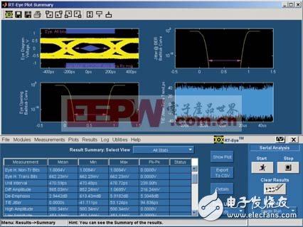
As an example, let’s look at the testing of Fibre Channel signals. With a data rate of 2.125 Gbps, a 7 GHz bandwidth oscilloscope like the Tektronix TDS7704B, along with a 5 GHz differential probe (P7350), is suitable for this task. A CDR (Clock Data Recovery) module is also essential, as the clock is embedded within the data stream. Additionally, real-time serial data analysis software like Tektronix RT-eye is used to analyze the signal.

This software can handle most of the Fibre Channel signal tests, including eye diagrams, jitter, rise and fall times, eye height and width, Jitter@BER, Dj, Rj, eye opening@BER, rate, UI, and even bathtub curves, histograms, and more. Figures 2 and 3 show the test results for a 2.125 Gbps Fibre Channel signal and a 2.5 Gbps PCI Express signal, respectively.
Finally, it's important to note a few key considerations during testing: pattern length settings, pattern type selection, phase-locked loop filter bandwidth, and the amount of data required for BER calculations. These factors significantly impact the accuracy and reliability of the test results.
110KV-220kv Oil Immersed Transformer
110Kv-220Kv Oil Immersed Transformer,Anti - Interference 110Kv Transformer,Low Loss 110Kv Oil-Immersed Transformer,High Load Capacity 110Kv Oil-Immersed Transformer
Tianhong Electric Power Technology Co., Ltd , https://www.tianhongtransformer.com