The maximum record length of the WaveExpert CIS timebase is 512 MS, and the sampling rate is almost fixed at 10 MS/s. The time base is not triggered, but requires an external clock that is synchronized with the input waveform. A clock frequency of 125 MHz to 13.5 GHz must be connected to the prescaler input and a clock frequency of 62.5 MHz to 125 MHz must be connected to the trigger input. The CIS time base does not support clocks below 62.5 MHz.
This article refers to the address: http://
The CIS timebase uses a phase-locked loop (PLL) to synchronize an internal clock of approximately 2.56 GHz to the external clock input. However, synchronization is not exact. It differs from the external clock by a known amount, based on an algorithm that sets the corresponding fraction in the PLL. The additional Divide By 256 generates approximately 10 MHz strobes from the internal 2.56 GHz clock. This strobe drives a sampler that samples the input waveform at a calculated rate of approximately 10 MS/s. The time between samples is approximately 100 ns. Multiple input waveform cycles will pass between samples. It does not require triggering, and once the time base is synchronized to an external clock, multiple samples can be acquired at approximately 10 MS/s. Note that it takes 0.4 seconds to acquire 4 MS samples.
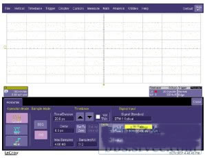
The CIS timebase requires multiple control inputs, including Bit Rate, PLL Bandwidth, Pattern Length, Samples/UI, and Ext. Divider.
Bit Rate
The Bit Rate control function must be set to the bit rate or frequency of the pattern, even if the pattern is a simple sine or square wave. Below is an example of a 10 GHz sine wave with bit rate set to 9 GHz instead of 10 GHz. The display cannot be recognized as a pattern.
Note that the loss of lock indicator in the horizontal descriptor box is red, indicating that the input clock rate is different from the Bit Rate. As an oscilloscope user, you must type the bit rate or frequency of the input signal in the Bit Rate control box.
PLL Bandwidth
The CIS time base has a PLL that synchronizes the strobe output to the clock input. The PLL has two bandwidth settings: Low and High, which correspond to approximately 10 kHz and 1 MHz, respectively, which are set using the PLL Bandwidth control function. The CIS time base has the lowest jitter on the Low setting. If you want to measure all jitter in a signal input above 10 kHz, you should use the Low setting. The PLL will track any jitter from DC to 10 kHz and jitter will not appear on the signal under test. If you want to measure all jitter in an input signal above 1 MHz and track DC to 1 MHz jitter, then use the High setting.
Pattern Length
The pattern length of the signal can be selected by setting Custom in the Std. Pattern selection box or by selecting a standard from multiple standards provided.
The figure below shows the pattern length of PRBS7 and 127. CIS has an outstanding feature that can display pseudo-random pattern sources without a trigger source. Below is a screenshot of a portion of the 2 Gbit/s pseudo-random pattern of 127 bits or 27-1 bits long.
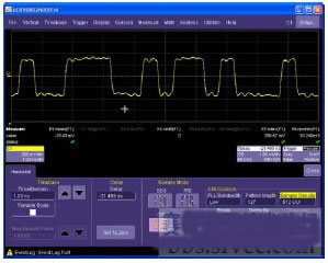
Any pattern length up to 231–1 or 2147483647 can be acquired under certain restrictions.
Samples/UI
You can use the Sample Density control to change the number of samples per bit period or unit interval (UI). This signal is the same as the signal at 8 S/UI above.
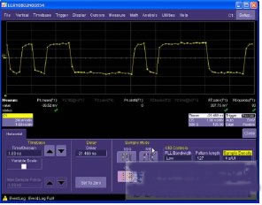
Note that the horizontal position in the pattern is different from the first screenshot. As the sample density changes, the internal PLL is reprogrammed to change the phase of the internal 2.56 GHz clock relative to the external 2 GHz clock. The result is that the starting phase of the pattern is unknown. As long as the Sample Density and Bit Rate are unchanged or the external signal is unchanged, the phase will remain the same.
Ext. Divider
Some code generators have an output clock that is divided by the pattern bit rate. Note that in the screenshot above, the Ext. Divider control function is followed by an input clock rate indicator that shows the actual clock input to the sampling oscilloscope.
CIS Jitter
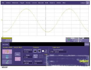
The CIS timebase has a time jitter of <250 fs rms. This can only be measured with a low-jitter source that has a large enough amplitude and a high enough frequency to ensure that vertical noise does not cause jitter. We measure jitter using a 10 GHz sine wave with an amplitude of approximately 6 dBm. The signal source is a sine wave generated by an Anri synthesis signal source. The estimated jitter of this source is less than 150 fs rms.
Below is a screenshot of the 10 GHz sine wave acquired by the CIS time base.
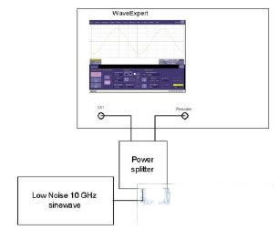
The following are techniques for measuring the use of CIS timebase jitter. Connect the oscilloscope to a low noise sine wave source. This is the setting used.
Graphic content:
Power splitter: power splitter
Low Noise 10 GHz sinewave: low noise 10 GHz sine wave
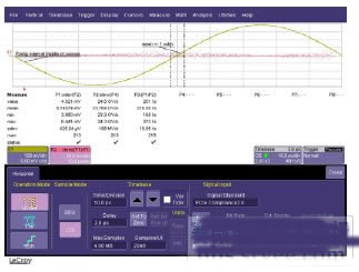
Set up the oscilloscope in the following way (see screenshot below). Set F1 = C1, F2 = eres(F1)-F1 and F4 = eres(F1). In both mathematical functions, Eres is set to 3. With F1 = C1, you can easily change the measurement channel by changing the source of F1.
The mathematical function F2 smoothes the sine wave, removes the noise, and then subtracts the original sine wave, leaving only the noise. Note that the pink F2 curve below the screen shows the noise at zero intersection and very little noise at the peak of the sine wave. The parameter P1 in the middle of the screen on F2 measures the standard deviation of the noise. The door on the right side of P1 and the door on the left side move to within ±0.2 grids in the middle of the screen.
The parameter P2 measures the slew rate of the smoothed sine wave in the mathematical function F4. The door to the right of P2 and the door to the left move to the center of the screen, measuring the slew rate of the same edge being measured.
P3 uses parameter calculus to obtain the ratio of P1 to P2 and calculate rms jitter.
When the signal amplitude is small, the voltage noise of the sampler must be considered. For example, in the above setup, the sampler's voltage noise is approximately 0.7 mV rms. Subtract this integral value from the standard deviation measured by F2 to obtain the actual standard deviation value:
Actual standard deviation = sqrt(5.145742-0.72)=5.098 mV rms.
The jitter is changed from 216.55 fs to 214.5 fs, and the jitter is slightly adjusted. However, if the amplitude of the sine wave drops, the standard deviation measured at zero crossing will decrease, and now the voltage noise of the sampler module 0.7 mV rms becomes more important. This can also happen if the frequency of the sine wave is reduced, the slew rate will drop, and the standard deviation of the noise at zero crossing will fall again.
If a higher bandwidth sampler is used, the voltage noise will be larger, and when measuring jitter using the above technique, voltage noise may have to be considered even if the amplitude is the same.
The following is the same setting, but the PLL Bandwidth is set to High.
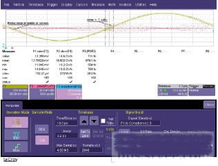
The increased jitter is due to increased source jitter in the time-base jitter of DC to 1 MHz during integration. Time jitter can be easily seen when the sine wave zero intersects. Again, the noise is very small at the peak of the sine wave, indicating that the vertical noise due to the signal source and the sampling module is very low.
Our company is specialized in supplying AC Bracket, AC Support, Air Conditioner Bracket, Air Conditioner Support Bracket. We could supply different type of brackets with different sizes. It could suitable for 0.75HP, 1. HP, 1.5HP, 2HP, 3HP, 4HP etc. Tell me the measurement, material and thickness. Our products are widely used in electronic appliances, lighting, switch, sanitary, sanitary ware, jewelry, watches, toys, furniture, gifts, handbags, umbrellas, doors and windows. Stainless Steel: SS201, SS301, SS303, SS304, SS316, SS416. Steel: Q235B, Q195, Q345.Brass: C36000, Bronze: C51000, C52100, C54400. Iron: 1213, 12L14, 1215. Aluminum: Al6061, Al6063.RUBBER: EPDM, NR, SBR, HNBR, NBR, CR, FPM...
Air Conditioner Bracket
Air Conditioner Bracket,Air Conditioner Support Bracket,Air Conditioner Support,Window Air Conditioner Bracket
ZHEJIANG ICE LOONG ENVIRONMENTAL SCI-TECH CO.,LTD. , https://www.ice-loong.com