Generally, the process of converting AC power into DC power is called rectification, the circuit that completes the rectification function is called a rectification circuit, and the device that implements the rectification process is called a rectification device or a rectifier. Correspondingly, the process of converting DC power into AC power is called inverter, and the circuit that completes the inverter function is called an inverter circuit, and the device that implements the inverter process is called an inverter device or an inverter.
The inverter is also called the power regulator. According to the use of the inverter in the photovoltaic power generation system, it can be divided into two types: independent power supply and grid connection. According to the waveform modulation method, it can be further divided into a square wave inverter, a staircase wave inverter, a sine wave inverter and a combined three-phase inverter. For the inverter used in the grid-connected system, it can be divided into a transformer type inverter and a transformerless type inverter according to the presence or absence of a transformer.
As mentioned above, there are many types of inverters, so special care must be taken when selecting the model and capacity. Especially in solar power systems, the efficiency of the inverter is an important factor in determining the capacity of the solar cell and the size of the battery.
Based on the basic principle and control strategy of the PV grid-connected inverter, the structure of the grid-connected inverter is designed. It adopts the front and rear two-stage structure of the built-in high-frequency transformer, namely the pre-stage DC/DC high-frequency boost and the rear-level DC. /AC power frequency inverter. The design mode has the advantages of simple circuit, stable performance, high conversion efficiency and the like.
Today, with increasingly tight energy sources, photovoltaic power generation technology is receiving more and more attention. The direct current generated by solar cells and wind turbines needs to be inverted by the inverter and meet the specified requirements before they can be connected to the grid. Therefore, the design of the inverter is related to whether the photovoltaic system is reasonable, efficient and economical.
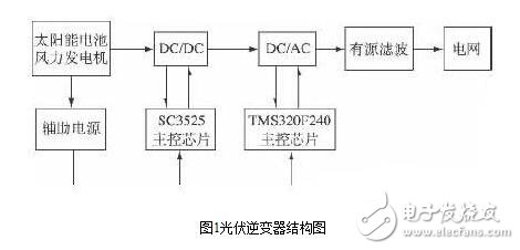
1. Principle structure of photovoltaic inverter
The structure of the photovoltaic grid-connected inverter is shown in Figure 1. It is mainly composed of a front-stage DC/DC converter and a rear-stage DC/AC inverter. The basic principle is to convert the low-voltage direct current into high-voltage direct current through high-frequency conversion technology, and then obtain 220V alternating current through the power frequency inverter circuit. The structure has the advantages of simple circuit, small no-load loss of the inverter power source, large output power, high inverter efficiency, good stability and small distortion.
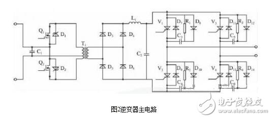
The main circuit of the inverter is shown in Figure 2. The control of the DC/DC module uses the SG3525 chip. The SG3525 is a dual-ended output SPWM pulse width modulation chip that generates a PWM waveform with a variable duty cycle for driving the gate of the thyristor to control the thyristor on and off, thereby achieving the purpose of controlling the output waveform.
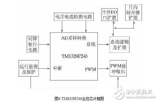
As a key module of the grid-connected inverter, the DC/AC module has higher control requirements. This design uses TI's TMS320F240 as the main control chip for collecting grid synchronization signals, AC input voltage signals, and adjusting IGBT gate drive. The circuit pulse frequency, through the software phase-locked loop control technology based on DSP chip, completes the frequency and phase control of the grid-connected current, so that the output voltage satisfies the same frequency and the same phase relationship with the grid voltage.
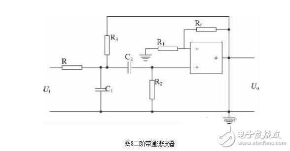
Filtering uses a second-order bandpass filter, which is a type of active filter that transmits signals in useful frequency bands to suppress or attenuate signals in unwanted bands. The utility model can effectively filter out the high-frequency interference waveform generated after the inverter, so that the voltage waveform after the inverter reaches the requirement of grid connection.
2, DC / DC control module
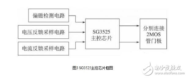
The SG3525 is a PWM control chip dedicated to driving N-channel power MOSFETs. The output of SG3525 is driven by push-pull output, which can directly drive MOS tube. It contains undervoltage lockout circuit, soft start control circuit and PWM latch. It has overcurrent protection function, adjustable frequency and maximum duty cycle. The two outputs are connected to two MOS tubes to control the breaking. In order to improve the effective control of the push-pull DC/DC high-frequency boosting process and improve the accuracy of the bandwidth modulation, a detection circuit is designed to detect the output current and voltage. And then feed back to the control chip. The detection circuit includes a bias detection circuit, a voltage feedback sampling circuit, and a current feedback sampling circuit. The structure of the SG3525 control module is shown in Figure 3.
3, DC / AC control module
3.1 TMS320F240 control core
TMS320F240 is a fixed-point digital signal processor chip of TI Company of USA. The hardware architecture is based on 16-bit data processing unit. It integrates high-performance DSP core, and has rich peripheral functions and fast processing speed. The peripheral circuit of DSP system includes clock circuit, reset circuit, power supply circuit, etc., with various signal detection circuits and drive circuits to achieve the requirements of waveform control, pulse width modulation and fault protection of the inverter system. 4.
3.2 voltage and current detection circuit
(1) Grid voltage zero-crossing detection circuit
After the inverter, the voltage of the alternating current must be in phase with the grid voltage and the same frequency can be connected to the grid. Therefore, the output voltage should be phase-locked. Since the output voltage signal is a sine wave, and the control chip can only recognize the TTL level signal, a circuit is needed to convert the sine wave signal into a TTL level signal that the control chip can recognize. In this design, the LV25P voltage sensor is used to collect and convert the grid voltage into a low voltage pulse signal with a phase equal to the grid voltage. After a set of comparator circuits, a set of low voltage square wave signals in phase with the grid voltage can be output. When the detected grid voltage exceeds zero, the output is high. The grid voltage zero-crossing detection circuit is shown in Figure 5.
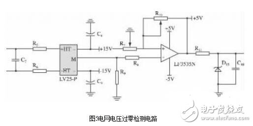
The square wave signal obtained by the grid voltage zero-crossing detection circuit is sent to the capture pin of the DSP chip through the double Schmitt inverter circuit, and the capture unit triggers the interrupt when the rising edge is detected, and the phase lock is performed.
(2) AC current detection circuit
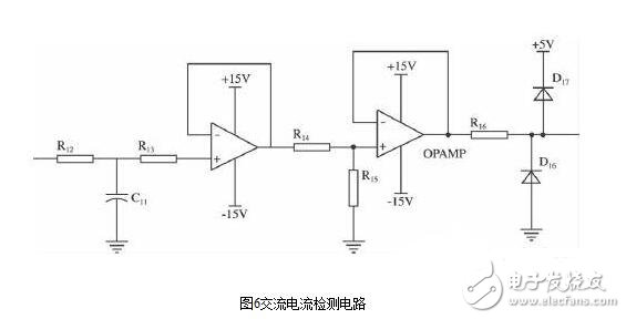
The AC current detection circuit uses the CSM300LT closed-loop current sensor. Figure 6. The CSM300LT is a current sensor that uses the Hall-effect closed-loop principle to measure AC current under galvanic isolation. When the AC power passes through the sensor, the sensor converts the current signal into a voltage signal and sends it to the signal conditioning circuit, which is processed and input to the pin of the DSP chip. The conditioning circuit consists of an RC filter circuit and two sets of integrated op amp isolation circuits.
4, auxiliary power supply
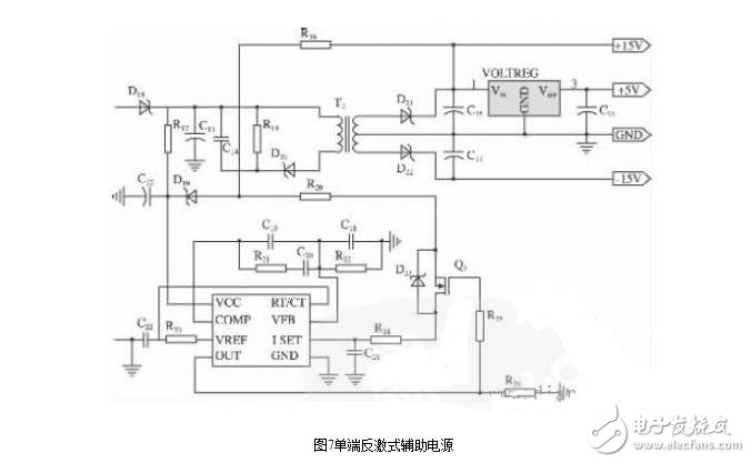
The control circuit of the inverter, the signal acquisition circuit and the switch tube drive circuit need different power supply, so an independent power supply is needed to supply power. The designed auxiliary power supply output voltage is +15V, -15V, +5V, respectively. It adopts single-ended flyback DC/DC topology structure, which is stable and reliable. The basic circuit of auxiliary power supply circuit is shown in Figure 7.
5, active filtering
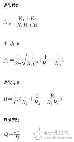
Active filtering uses a second-order bandpass filter, which is a frequency selective network composed of an operational amplifier and a RC component. It is used to filter out the higher harmonics generated during the inverter process. The principle is to set the circuit parameters. A signal in a certain passband range is allowed to pass, and a signal lower than the lower limit frequency of the passband and higher than the upper limit frequency is attenuated or suppressed, as shown in Fig. 8.
As an important part of the development and utilization of new energy, photovoltaic power generation has far-reaching significance for solving energy and environmental problems. The inverter is an important part of the photovoltaic power generation process. In this paper, the topology of the inverter system is studied. The inverter system with high-frequency boost and full-bridge inverter as topology structure is designed. Combined with active filtering, it plays a certain role in the further development and utilization of solar energy.
PV inverter installation and maintenance1. Before installation, you should first check whether the inverter is damaged during transportation.
2. When selecting the installation site, it should be ensured that there is no interference from any other power electronic equipment in the surrounding area.
3. Before making electrical connections, be sure to cover or disconnect the DC side circuit breakers with opaque materials. When exposed to sunlight, the PV array will generate dangerous voltages.
4. All installation operations must be performed by professional technicians only.
5. The cables used in the photovoltaic system power generation system must be firmly connected, with good insulation and appropriate specifications.
6. All electrical installations must meet local and national electrical standards.
7. The inverter can be connected to the grid only after obtaining the permission of the local power department and all electrical connections are completed by professional technicians.
8. Before performing any maintenance work, first disconnect the electrical connection between the inverter and the grid, and then disconnect the DC side electrical connection.
9. Wait at least 5 minutes until the internal components are discharged before performing maintenance work.
10. Any fault that affects the safety performance of the inverter must be eliminated immediately before the inverter can be turned on again.
11. Avoid unnecessary board contact.
12. Observe the static protection code and wear an anti-static wrist strap.
13. Pay attention to and follow the warning signs on the product.
14. Visually inspect the equipment for damage or other dangerous conditions before operation.
15. Pay attention to the hot surface of the inverter. For example, a heat sink of a power semiconductor or the like maintains a relatively high temperature for a period of time after the inverter is powered off.
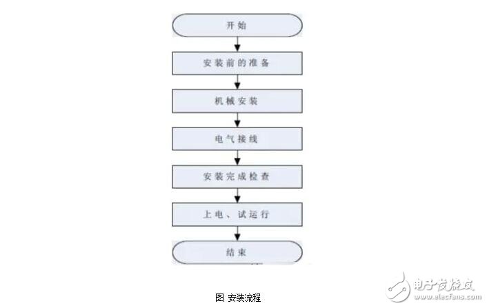
PV inverter installation process
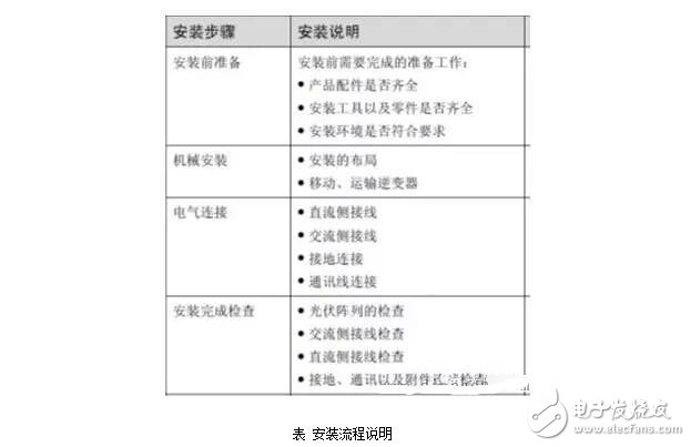
The overall installation process of the inverter is shown in the figure, and the installation process description is as shown in the table:
Inverter installation location requirements
1. Do not install the inverter in direct sunlight. Failure to do so may result in additional internal temperature of the inverter, which will derate the inverter to protect internal components. Even the temperature is too high, causing the inverter temperature to malfunction.
2. The installation site should be strong enough to support the weight of the inverter for a long time.
3. The ambient temperature of the selected installation site is -25 °C ~ 50 °C, and the installation environment is clean.
4. The ambient humidity of the selected installation site is not more than 95%, and there is no condensation.
5. There should be enough clearance in front of the inverter to make it easy to observe the data and repair.
6. Try to install it away from the living of the residents, and some noise will be generated during the operation.
7, the installation place to ensure that it will not shake.
A high-speed slip ring is an electromechanical device that allows electrical current to pass between a stationary and a rotating assembly. It is typically used in applications where the speed requirement exceeds that which is achievable with a standard slip ring. High-speed slip rings are available in a variety of sizes and configurations to meet the needs of most applications. They are commonly used in military, aerospace, and medical applications where speed and reliability are critical.
The speed is required to be at least tens of thousands of revolutions per minute, the structure of the Conductive Slip Ring directly determines the contact of high speed, as well as the size of impedance. High-speed slip ring materials have high wear resistance, high life characteristics, and multi-contact contact can ensure signal transmission and power reliability, with the development of science and technology, high-speed slip rings will be more and more widely used.
If you need to transfer large amounts of data or power between two stationary objects, a high-speed conductive slip ring is what you need. Traditional slip rings only offer a few thousand revolutions per minute (RPM), which is more than enough for most applications, but can be limiting in some circumstances. Some applications, like those found in the medical or military field, require speeds of tens of thousands of RPM in order to function properly. That's where our high-speed conductive slip ring comes in. With speeds up to a certain range, it can handle even the most demanding applications.
High Speed Slip Ring,Rotary Slip Ring Electrical,Slip Electrical Connector,Hydraulic Rotary Joint
Dongguan Oubaibo Technology Co., Ltd. , https://www.sliproubos.com