introduction
With the development of the machinery industry and the continuous improvement of the scientific research level, the experimental and testing methods of mechanical transmission products have continuously put forward higher requirements. For a long time, the development of transmission test rigs in China has basically remained at the level of traditional manual methods. The main types are mechanical power flow closed test rigs with mechanical or hydraulic pressure and electric power closed test rigs with generators. . These test stands have their own common shortcomings due to energy saving or due to loading. However, the degree of automation is low, it is difficult to test according to the pre-designed test process, and it is impossible to simulate the actual working conditions for various mechanical transmission products. Influence, so the test results are inevitably quite far from the actual situation, which greatly affects the direct guidance of the test data on the design and production of mechanical transmission products. Most of the transmission test platforms adopt manual operation mode. The monitoring of the test process and the collection and processing of test data are both cumbersome and low in accuracy, and it is difficult to realize multi-parameter automatic control and failure determination.
In order to make up for the above deficiencies, we propose a new scheme - based on a mechanically closed mechanical transmission test bench, driven by an AC motor, using an AC variable frequency speed control system to achieve stepless speed regulation, digital hydraulic loading control system to achieve no Stage loading and simulation of load spectrum. The control system adopts object-oriented programming technology and layered design ideas, integrates various control algorithms and data processing algorithms, provides a friendly human-computer interaction interface, and visualizes the data collected by the computer.
l The composition and working principle of the multifunctional test bench
According to the power transmission principle and loading method of the test bench, the test bench can be divided into three categories: open power flow type, closed power flow type and electric power flow closed type. The mechanically closed power flow test rig (Fig. 1) has a wide range of applications because it can be used for large power tests with low-power prime movers and low power consumption, without the need to install energy-consuming devices, and to save energy. In a closed system, one end of the power flows out and flows from the other end to form a closed loop flow, so that only a small amount of energy can be input from the outside to keep the system running. The energy supplied by the motor is mainly to compensate the friction power loss of each component in the closed system during operation, and its value is about 10% to 15% of the closed power value. 
2 system plan
The test bed control device should be able to control the speed and load change in real time on-line, with fast response and strong anti-interference ability; data acquisition and processing should satisfy the wide sampling range, can realize sampling under different frequencies, and automatically process the analysis data. The analysis results show that the operation interface is convenient and easy to control.
2.1 Hardware Solution
The hardware method mainly uses an ASIC and a specially designed hardware circuit board to complete the collection, conversion, averaging, amplification, counting, filtering, etc. of the torque speed signal. The hardware circuit is complicated. Only the power supply must supply various regulated power supplies such as positive and negative 24V, 10V, 5V, etc. The structure is complex, the reliability is low, and the function is single. Only various index values ​​can be obtained instantaneously, and cannot be stored, displayed and printed. Wait.
2.2 Software Solutions
The system is built on the Windows2000 platform and is compiled in VC++ language. The inverter, motor, carrier, sensor, data acquisition card, etc. are abstracted into classes, and the equipment is modularized. The system can be expanded, modified, added, combined, and realized for the replacement of the test piece and equipment of the test bench. Different experiments have greatly improved the applicability of the test rig and its control system.
2.3 design
The test bench is controlled by a high-end industrial control computer with a single-chip system to control the motor speed control system and the hydraulic loading system. The industrial computer not only has the controller, but also has the functions of recorder, oscilloscope, dynamic signal analyzer, etc. It can also conveniently set different alarm parameters such as speed, torque and temperature and failure judgment indicators according to the needs of different experiments. The overall design scheme is shown in Figure 2. 
3 computer data acquisition, testing and control
3.1 computer data acquisition, testing
After configuring the parameters of the CB2000 card torque meter and PCL-812PG multi-function data acquisition card, the performance parameter test is through the JC2B torque speed sensor (as shown in Figure 3) and the matching CB2000 card torque meter. Data acquisition, processing, and control tasks are performed by a computer. It can be operated in the form of man-machine dialogue. According to different tasks, it can be tested according to standard or non-standard test methods. The test results can be displayed on the screen in digital or curved form, or output to the printer, and can also be saved. In the database. 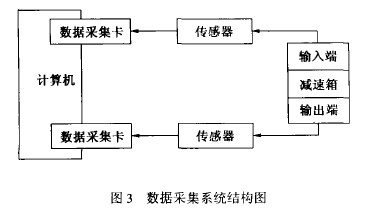
3.2 Load and speed control
The voltage output signal is output to the inverter and digital valve through the analog output port of PC812-PG to control the speed and load.
4 Design features and uses of the test bench
The design combines the traditional mechanical transmission test bench with the emerging computer technology. The computer realizes the digital control of the rotational speed and load, and makes the rotational speed and load sensitive. It can better simulate the actual working conditions and realize the experimental platform. Torque and speed signals are accurate, online, real-time, and high-speed acquisition and processing. The inverter can realize constant torque speed regulation and constant power speed regulation, which saves the inconvenience of using the control cabinet in the past. The test bench also has strong development potential, and the scope of application of the test bench can be increased through the continuous upgrade of the software version and a small amount of hardware improvement.
Applicable mechanical transmissions include cylindrical gear reduction gearboxes, transmissions, bevel gears, automobile drive axles, worm gear reducers, planetary gear reducers, chain drives, transmissions and the like.
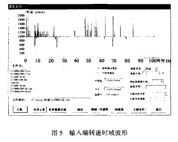
The following is the 1k data of the speed signal with the load constant of M=130N•m and the input of the reducer N=1000r/min (as shown in Fig. 4 and Fig. 5), and the Fourier transform or wavelet transform (slightly) can be performed on the system. Perform analysis and troubleshooting. Fig. 6 is a graph showing the transmission efficiency curves at different speeds and different loads. The input speeds of the curves from top to bottom are 600r/min, 800r/min, 1000r/min, 1200r/min, and 1600r/min, respectively. 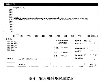
When the test bench rotates, it consumes a part of the power of the motor, which only changes with the change of the rotational speed of the drive shaft. The main factors causing this power loss are the friction of the transmission member during rotation, the increased friction due to machining and assembly errors, and the oil, air resistance and other dynamic loads. As the speed increases, the transmission efficiency will decrease under the same load due to the increase in power loss. It can be seen from Fig. 6 that under the same load, the higher the rotational speed, the lower the efficiency, which also indicates that the test results of the test bench are consistent with the theory. The test bench is a 9-stage precision closed cylindrical gear transmission. The theoretical value of the transmission efficiency should be about 96%. Due to the friction of the motor, loader, actuator, bearing, etc., oil loss, assembly error and measurement error, The calculated transmission efficiency is made lower than the theoretical value. 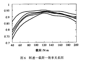
in conclusion
The new multi-functional mechanical transmission test bench is based on a mechanical power flow closed mechanical transmission test bench, with a computer as the core, a frequency converter and an AC motor as a speed control system, and a hydraulic pump station and a loader to form a loading system to simulate the actual work. In this case, the torque and speed data are used to obtain torque and speed data, and together with the cylindrical gear reduction box constitute a mechanical transmission test bench with closed power flow. The entire test bench uses a computer as the control and processing center. The design scheme fully reflects the flexible use of computer resources and digital technology. The test bench developed in this paper has been successfully used in the test of system transmission power and mechanical product load. Many tests have shown that the test bench has greatly improved the degree of automation compared with other similar test stands, and the ability to simulate actual working conditions is significantly enhanced.
references
1 Wang Jinge, Chen Yu, Xiang Zhongfan, etc. A multi-function numerical control dynamic simulation mechanical transmission test bench. Machinery, 1988 (25)
2 Zhu Ying, Xiang Zhongfan. Research on Control and Testing Technology of Object-Oriented Mechanical Transmission Test Bench [Master Degree Thesis]. Chengdu: Sichuan Institute of Technology, 2003
3 Zhu Xiaolu, Yi Bingcheng and so on. Gear experimental technology and equipment. Beijing: Mechanical Industry Press, 1998
4 Fan Chengben. Gear strength and experiment. Beijing: Mechanical Industry Press, 1979
This article refers to the address: http://
Fiber Optical Splice Closure
Fiber optic splice closures are made of excellent engineering plastics. Sijee supply different ports types, fittings and different fiber optic core numbers for horizontal and dome fiber optic splice closures.
Sijee's Splice Closure is suitable for protecting optical fiber splices in straight through and branching applications, and can be used in aerial, duct and direct buried fiber optic cable projects.Horizontal Fiber Optic Splice Closure
Horizontal Fiber Optic Splice Closure,New Horizontal Fiber Optic Splice Closure
Sijee Optical Communication Technology Co.,Ltd , http://www.sijee-optical.com