Abstract: The car anti-theft system is developed using GPS/GSM technology. The system uses the GPS positioning technology to obtain the position of the vehicle, determines whether the vehicle is moving, and can transmit the vehicle location information to the user through the GSM network. The user can set the working status of the system through the GSM network. The internal control of the system is completed by the single-chip microcomputer, which receives GPS data and commands from the user, and gives corresponding processing after analysis. The positioning accuracy of the system is within 10 meters, and the user can be notified in time after the vehicle is stolen, and the expansion can add more functions.
Keywords: single chip microcomputer; global mobile communication system; global positioning system; TC35i
This article refers to the address: http://
O Introduction With the popularity of vehicles and other vehicles, wireless communication technology and global satellite positioning (GPS) technology are gradually applied to areas such as vehicle monitoring. Whether it is the monitoring of special vehicles such as police cars and cash trucks, or the anti-theft monitoring of ordinary cars, wireless communication and GPS technology play an important role. At present, mobile wireless communication methods mainly include: a. Cluster mobile communication method; b. DSRC (dedicated short-range) communication method; c. GSM (Global System for Mobile Communications). Among them, the GSM method has a large data range, good data confidentiality, convenient use, and low cost. Combined with the GPS system, the GSM system can transmit the position, speed, driving direction and other status information of the vehicle to the vehicle owner's handheld terminal or monitoring center through the wireless communication link to realize the monitoring of the vehicle.
In the services provided by the GSM system, the voice service and the data service need to establish a connection through dialing, and the billing starts once the connection is established. The GSM short message service does not need to establish a dial-up connection, and only needs to send the information to be sent to the short message center, and then forward the short message center to the target user terminal. The short message service is charged according to the number of sent short messages. As long as the short message is limited to 140 bytes each time, the data length is sufficient to transmit GPS positioning information. It can be seen that the data transmission using the GSM short message service can fully utilize the mobile communication network with wide coverage, realize the positioning of the remote movable target in an inexpensive manner, and is more suitable for the anti-theft monitoring of the automobile. This paper uses PIC18F2450 microcontroller, SIRF third GPS receiver module and GSM module TC35i to design the vehicle anti-theft monitoring terminal.
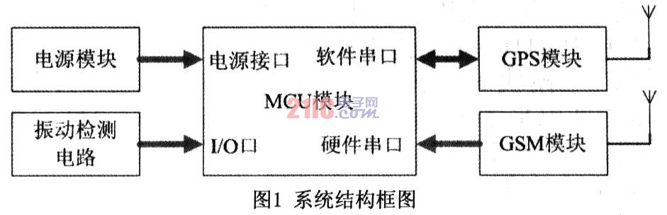
1 Vehicle terminal hardware design The vehicle terminal is mainly composed of four parts, namely GSM module, GPS receiver module, single chip control circuit and power supply circuit. The GPS module is responsible for receiving the positioning data; the GSM module sends and receives short messages under the control of the single chip microcomputer; the single chip control circuit analyzes the GPS positioning data and makes corresponding processing according to the user's settings. The power supply circuit provides +5V DC voltage for the single-chip microcomputer and GPS module by the 7805. The LM2941CS then regulates the +5V DC voltage to +4.2V for the GSM module. The structural block diagram of the system is shown in Figure 1.
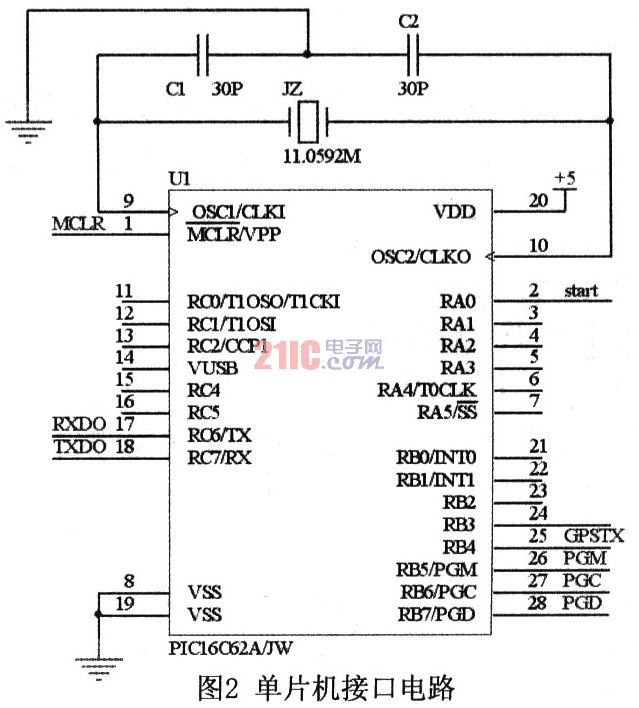
1.1 Microcontroller Control Circuit The system uses Microchip's PICl8F2450 as the MCU. The chip is a 28-pin high-performance single-chip microcomputer adopting nanoWatt technology, which has the advantages of high reliability, low cost, low power consumption and small size. It has 16k bytes of Flash program memory and 768 bytes of RAM inside, supporting online programming and debugging. There is only one universal asynchronous serial port inside the microcontroller. In order to be able to communicate with GPS and GSM modules at the same time, the MCU needs two serial ports. However, if you choose a single-chip microcomputer with dual serial ports, it will increase the cost. Therefore, the system uses the PICl8F2450 common I/O port and the library function provided by the C compiler of the series of single-chip microcomputers to design a software serial port. The hardware serial port inside the MCU communicates with the GSM module through the 17-pin and 18-pin, and the software serial port receives the GPS signal through the 25-pin. The 2 pin of the MCU is used as the start pin of the GSM module. The interface circuit is shown in Figure 2.
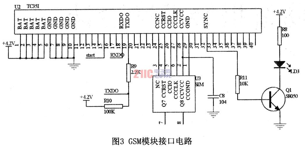
1.2 GSM module The GSM module is responsible for transferring information between the vehicle terminal and the monitoring user. This system adopts Siemens GSM module TC35i. The TC35i module is an industrial-grade GSM module that supports Chinese short messages. It works in GSM900 and GSMl800 dual-band and can transmit voice and data signals. The TC35i's data interface (CMOS level) transmits commands and data in both directions via the AT command. It supports SMS (short message) in Text and PDU formats, and can be restarted and recovered by AT commands or shutdown signals.
The TC35i module has 40 pins and is divided into five categories: power supply, data input/output, SIM card, audio interface and control. Its working voltage is 4.2V, and the module's power supply voltage will automatically shut down if it is lower than 3.3V. The current peak can be as high as 2A due to the module transmitting the signal. Therefore, the module has higher requirements on the power supply. The system adopts a switch-type adjustable high-performance microwave circuit dedicated voltage regulator chip LM2941CS, which can provide a large current stable voltage output. When using the TC35i module, its start pin IGT must be added a time longer than 100ms to enable the TC35i to be put into operation. The data input/output interface of the TC35i module complies with the ITU-T RS232 interface standard and supports the standard AT command set.
The interface circuit between the GSM module and the MCU is shown in Figure 3.
1.3 GPS module The GPS module used in this system is SIRF third-generation high-sensitivity leaded GPS receiver module SIRF star III. The chip positioning accuracy is less than 10 meters, and the cold boot/warm boot/hot boot time is 42s/38s/8s respectively, and up to 20 satellite channels can be tracked at the same time. There is a rechargeable battery inside, which can store ephemeris data for quick positioning. The serial port data format is TTL level data output, the communication rate is 4800 communication baud rate, and the GPS full data is output once every second. The module GPS antenna adopts MMCX interface, the data line interface is 6-wire connector, and the cable output is very simple to use. Only three output lines are needed, and the first leg is connected with a 3.5-5.5V DC positive power supply. The fifth foot is the power ground, and the second foot is the GPS output line. It is a TTL level serial port signal. The high level is greater than 2.4V, the low level is less than 0.4V, and the output drive capability is 2mA. The single-chip interface; the sixth foot is the second signal output, and a pulse signal of about 0.2V with a width of 10ms is output every second for timing. Since the module only sends data to the single-chip microcomputer without receiving data from the data, the single-chip microcomputer in the system uses the software serial port to communicate with it, and the second leg of the MMCX interface can be connected to the 25-pin of the single-chip microcomputer.
2 car terminal software design
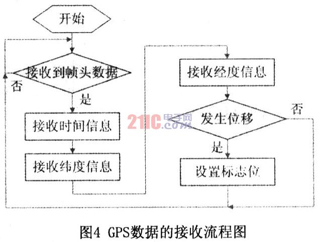
2.1 Receiving GPS Positioning Data By default, the GPS receiving module SIRF star III outputs positioning data once per second, usually using the $GPRMC streamlined data format, which contains the longitude, latitude, and speed (nautical mile/hour) of the target. Important information such as the direction of the movement, the year, the month, the hour, the minute, the second, the millisecond, whether the positioning data is valid or invalid. The statement format is as follows:
$GPRMC, <1>, <2>, <3>, <4>, <5>, <6>, <7>, <8>, <9>, <10>, <11>, <12> , *hh
<1>: Represents UTC local time. The format is "hours, minutes and seconds", and the hour, minute and second are both two.
<2>: Represents the working status. “A†indicates data is available, “V†indicates receiver alarm, and data is not available.
<3>: Represents latitude data. The format is "degrees. points."
<4>: Represents the latitude hemisphere, which is "N" or "S".
<5>: represents longitude data. The format is "degrees. points."
<6>: represents the longitude hemisphere, which is "E" or "W".
<7>: represents the ground speed, the range is 000. O ~ 999.9.
<8>: Represents the heading to the ground, ranging from 000.0 degrees to 359.9 degrees, with 0 degrees in the north, 90 degrees in the east, 180 degrees in the south, and 270 degrees in the west.
<9>: Represents UTC local time, and the format is “Day, Month, Month, Year and Yearâ€.
<10-12>: These three data are generally not used.
Each positioning data starts with "$" and ends with a carriage return. The software needs to realize the two functions of receiving and analyzing GPS data. The flow chart is shown in Figure 4.
2.2 GSM module control and short message processing The MCU can send AT to control the GSM module TC35i, send text messages commonly used Text and PDU mode, use Text mode to send and receive SMS code is simple and easy to implement, but the disadvantage is that it does not support Chinese SMS The PUD mode not only supports the Chinese mode, but also sends English text messages.
The MCU mainly transmits two types of information through the GSM module: one is to receive the user's settings and request commands, and to give a reply after processing; the other is to send an alarm to the user when the MCU determines that the car has moved in the armed state. And location information.
The format of user settings and request information is shown in Table 1.

The main program flow chart of the microcontroller is shown in Figure 5.
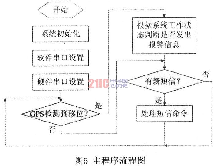
When the user receives the location message, the location of the vehicle can be determined. Mobile phones using S60 and PPC support Google mobile maps, such as NOKIA N82, launch Google Maps, select the network connection method WAP, input the received latitude and longitude data, and locate the vehicle location on the map.
3 Conclusion After testing, the system can achieve positioning within 10m accuracy in urban road environment, and can provide alarm location service to users according to user settings. The system is easy to operate and easy to install. Through the expansion of hardware and software, other functions can be realized, such as the function of expanding the system by adding a vibration detecting circuit, and sending an alarm message to the user when the car is hit or hit.
1.ANTENK Male Pin Header Series in Headers are a full range headers in a variety of configurations including Single, Dual and Three rows, Straight or Right Angle in Thru-Hole or SMT mounting. Their close tolerance .025" sq. posts are smoothly finished and taper tipped to eliminate insertion damage to the PCB or mating connector. ANTENK Pin Headers can be easily cut into exact sizes as required. Options include stacked insulator versions and choice of tin, gold or selective gold plating.
2.Our products are widely used in electronic equipments,such as monitors ,electronic instruments,computer motherboards,program-controlled switchboards,LED,digital cameras,MP4 players,a variety of removable storage disks,cordless telephones,walkie-talkies,mobile phones,digital home appliances and electronic toys,high-speed train,aviation,communication station,Military and so on.


SPECIFICATIONS:
Current Rating: 0.75Amp
Insulation Resistance: 1000M ohms min
Contact Resistance: 20M ohms max
Dielectric Withstanding: AC500V
Operating Temperature: -65°C to +125°C
Contact Material: Brass
Insulator Material: PA6T,UL94V-0,Color:Black
Male Pin Headers
Male Pin Headers,Pin Male Straight Box Header,Smd Pin Headers,Long Pin Male Header
SHENZHEN ANTENK ELECTRONICS CO,LTD , http://www.antenk.com