Semiconductor switching devices are polar, so the basic principle of turning on and off each other to determine the polarity of the switching device or the dual device of the switching diode should be noted. Of course, the dual device of the diode is also a diode, and the dual device of the switch is still a switch.
Figure 1 (a) is a series transistor original circuit, as shown in Figure 1 (b) its dual circuit. The switch tube V and V' are dual, the voltage source and the current source are dual, and the resistor R and the conductance G are dual. The positive direction of each branch in the circuit is given, called the directional branch. A directed graph consisting of a directed branch can draw a directed main circuit diagram of either circuit. When drawing a dual directed graph, the dual directed branch must be at 90° to the corresponding branch in the original graph, and understand the positive direction rule of the dual graph.
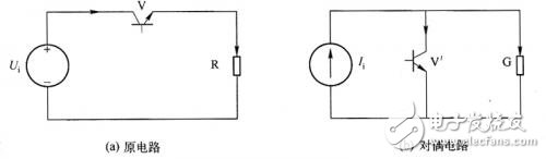
Figure 1 transistor switching circuit
Rule 1: The clockwise direction of the original circuit is the positive direction of the cell current, and the voltage polarity of the independent node in the dual circuit (for the reference node) is positive. In the original circuit, the directional branch containing the passive component is rotated 90° counterclockwise to obtain its dual directional branch.
Rule 2: The potential rise U in the positive direction of the cell current in the original circuit is dual with the current source I flowing to the independent node in the dual circuit. In the original circuit, the directional branch of the voltage source U (the current is in the direction of the potential rise) is rotated 90° clockwise, that is, the direction of the current source I in the dual directional branch is obtained.
When the ideal switch is turned on, it can be regarded as a resistor with a resistance of zero; when it is turned off, it can be regarded as a resistor whose resistance is infinite (∞). Therefore, when the polarity of the dual switch tube is sought, the directional branch including the switch can be handled in the same manner as the directional branch containing the passive component. Therefore, the rule for the polarity of the dual switch tube is as follows.
Rule 3: The directional branch including the switching tube V is rotated 90° counterclockwise to obtain a directional branch containing the dual switching tube V', so that the polarity of the dual switching tube V' can be determined.
As shown in Fig. 2(a), the directed graph of the original circuit is as shown in Fig. 2(a), and Fig. 2(b) shows the process of applying the above rule to find the dual directed graph: applying rule 1 to determine the directional branch containing G Direction; application rule 2 determines the direction of the directional branch containing current source Ii; application rule 3 determines the direction of the directional branch containing V', so that the polarity of the dual switch tube V' can be determined.
Finally, the directed graph of the dual circuit is obtained, as shown in Figure 2(c).
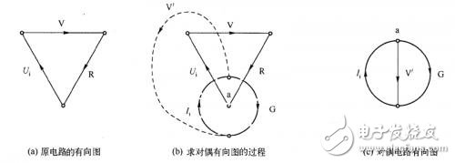
Figure 2 is a directed graph of the transistor switching circuit
To find the rule of the polarity of the dual switching diode, take the simplest rectifier circuit shown in Figure 3 as an example, as follows:
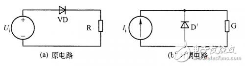
Figure 3 diode rectifier circuit
Figure 3 (a) is a diode rectifier circuit, as shown in Figure 3 (b) is its dual circuit. 4 is a process of constructing a directed graph with a dual circuit as shown in Fig. 3(a). Figure 4 (a) is a directed graph of the original circuit, as shown in Figure 4 (b) for the process of the dual directed graph, as shown in Figure 4 (b) and Figure 2 (b), can be seen using rules 1, rules 2 can determine the direction of the directional branch containing G and current source I. When determining the polarity of the dual diode D', it is noted that in the rectifier circuit of Fig. 3(a), the diode D is in the forward conduction state, and the dual diode D' should be in the reverse-off state, as shown in Fig. 3(b). Shown.
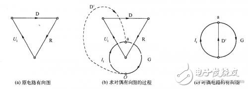
Figure 4 is a directed diagram of the diode rectifier circuit
Comparing Fig. 3(b) and Fig. 1(b), it can be seen that the polarities of the dual diode D' and the dual switch transistor V' are reversed. Finding the polarity rule of the dual switching diode is the opposite of the polarity of the dual switching transistor, as in rule 4.
Rule 4: The directional branch containing diode D is rotated 90° clockwise to obtain a directional branch containing dual diode D' so that the polarity of the dual diode can be determined.
30-50W Solar Street Lights,30W Solar Street Light,45W Solar Street Light,50W Solar Street Light
Yangzhou Bright Solar Solutions Co., Ltd. , https://www.solarlights.pl