Original authentic fake one lost ten
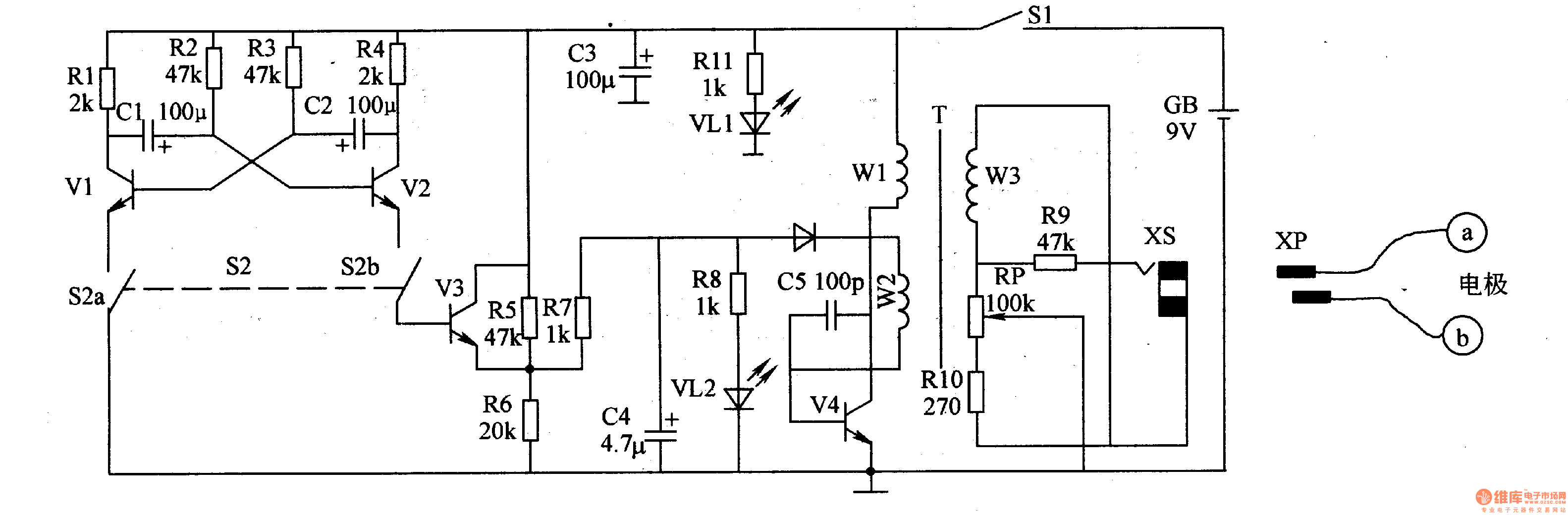
The power circuit is composed of a power switch S1, a battery GB, a filter capacitor C3, a current limiting resistor R11, and a power indicating LED VL1.
The square wave pulse oscillator is composed of resistors R1-R4, capacitors C1, C2, and transistors V1, V2.
The control circuit is composed of a control switch S2 (S2a, S2b), a transistor V3, and a resistor R5-R7.
The spike oscillator consists of resistors R5-R8, capacitors C4, C5, LED V愧, diode VD, transistor V4, and windings W1, W2 of pulse transformer T.
The pulse voltage output circuit is composed of a winding W3 of T, a resistor R9, R10, a potentiometer RP, an output socket XS, a plug XP, and electrodes a and b.
Turn on Sl, GB provides a 9V working voltage for the square wave pulse oscillator, control circuit and spike oscillator, and also VLl is illuminated by RlI current limiting buck.
When S2 is disconnected, the square wave pulse oscillator does not work, V3 is in the off state, the spike oscillator oscillates, VL2 flashes, and a low frequency spike pulse voltage is generated on the winding W3 of T. The pulse voltage passes through R9, RlO. After RP current limiting and partial pressure adjustment, XS and XP are applied to electrodes a and b.
When S2 is turned on, the square wave pulse oscillator is energized to generate a constant amplitude square wave pulse, so that V3 is turned on intermittently, and the spike pulse oscillator is modulated. At this time, the pulse voltage on the electrodes a and b is a low frequency square wave pulse. Voltage.
Adjusting the resistance of the RP can change the stimulation intensity of the pulse voltage to the human body.
Component selection
Rl-Rll uses 1/4W metal film resistor or carbon film resistor.
The RP uses a small synthetic carbon film potentiometer with a switch (power switch Sl).
Cl-C4 selects aluminum electrolytic capacitors with a withstand voltage of 16V; C5 uses high-frequency ceramic capacitors or CBB capacitors.
VD selects 1N4148 type silicon switch diode for use.
Both VLl and VL2 use high-brightness light-emitting diodes of φ3mm.
Vl-V3 selects 3DG8 or S9014 type silicon NPN transistor for use; V4 selects 2N5551 or 3DG84 type silicon NPN transistor for use.
S2 uses a small bipolar two-position switch.
GB uses a 9V laminated battery.
T uses the core and skeleton of the output transformer of the semiconductor radio: the windings W1 and W2 are wound with 50-60 å„ each of the φO.2mm enameled wires; the winding W3 is wound with 800-1000 turns of φ0.09mm enameled wire.
Marine Diesel Engine 4000Kw,Water Cooled Diesel Marine Engine,Marine Diesel Engine 8000Kw,Direct Injection Diesel Engine
Jinan Guohua Green Power Equipment Co.,Ltd. , https://www.guohuagenerator.com