In order to solve the problem of incompatibility of air conditioner remote control, a smart air conditioner remote controller based on Atmega16 single chip microcomputer was designed. The remote controller uses the method of measuring the pulse width to learn the infrared signal, and uses the run length coding algorithm to compress and store the data, and uses the internal timer PWM mode of the single chip to generate the infrared carrier, which successfully realizes the learning and reproduction of the infrared remote control, and Controlled by the host computer. The running test shows that the intelligent remote control has flexible operation and stable performance, and provides a new scheme for the design of the intelligent remote controller.
1 Introduction <br> This paper designed a smart learning infrared remote control for air-conditioning equipment, using the method of recording pulse width, successfully realized the learning and reproduction of a variety of infrared air-conditioning remote control signals, and truly realized the "universal". Based on the overall structure and hardware design of the system, this paper studies the software design and implementation of system learning, transmission and communication functions in detail.
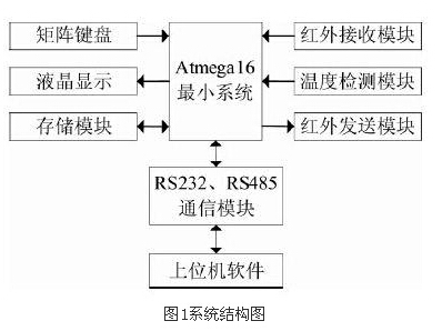
2 system overall structure and hardware design <br> The system adopts modular design, each module is connected to the main control chip through the interface circuit. The main modules are: matrix keyboard, liquid crystal display, storage module, infrared transmitting module, infrared receiving module, RS232, RS485 communication module, and temperature detection module. The system structure diagram is shown in Figure 1.
The system uses Atmega16 as the main control chip. Atmega16 has 16K bytes of in-system programmable Flash, 512 bytes of EEPROM, 1K bytes of SRAM, 32 general purpose I/O lines, and 32 general working registers for boundary scan. JTAG interface, support for on-chip debugging and programming, three flexible timer/counters (T/C) with compare mode, on-chip/out-of-interrupt, programmable serial USART, general-purpose string with start condition detector Line interface, 8-channel 10-bit ADC with selectable differential input stage programmable gain, programmable watchdog timer with on-chip oscillator, one SPI serial port, and six power-saving options that can be selected via software mode. The chip is powerful enough to meet system design needs and provides ample room for expansion. The main control chip uses an 8MHz crystal oscillator, and the crystal oscillator circuit is close to the main control chip to minimize input noise. The reset circuit uses a low level reset.
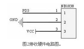
The matrix keyboard adopts 3*3 design and 8 function keys are set to facilitate manual operation. A mode switch button has been designed separately to switch between learning, transmitting and communication modes. In order to realize the learning function, the infrared receiving module uses an integrated receiving head NB1838, whose photoelectric detection and preamplifier are integrated in the same package, and the center frequency is 37.9KHz. The epoxy package structure of NB1838 provides a special infrared filter. The optical device is highly protective against natural light and electric field interference. NB1838 amplifies, detects, and shapes the received infrared signal, and modulates the infrared code to obtain the TTL waveform. After the inverter is inverted, it is input into the single-chip microcomputer, and then further processed by the single-chip microcomputer, and stored in the EEPROM. The receiving circuit is as shown in FIG. .
Considering that the system requires a large storage space, a separate storage module is designed. The selected EEPROM is AT24C64, which provides 8KB capacity. It communicates with the Atmega16 TWI interface through the IIC protocol, and stores the learned infrared commands here. Electricity is not lost.
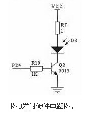
In the transmitting mode, the system reads the corresponding data information from the EEPROM, and uses the amplifying circuit composed of the transistor 9013 to transmit the modulated infrared signal through the high-power infrared transmitting tube. The transmitting circuit is shown in Figure 3. In the non-transmitting state, the triode works in the off state, and the infrared transmitting tube does not work, which is beneficial to reducing power consumption and prolonging the service life of the infrared transmitting tube. After actual testing, the launch distance can reach about 10m.
In the communication mode, the system communicates with the host computer through the RS232 circuit, and uses the DS18B20 feedback temperature information when communicating with the host computer. The DS18B20 one-line bus design greatly improves the system's anti-interference, unique and economical. The system also adds an RS485 module to facilitate networking to control multiple infrared devices. RS485 only needs to connect the "A" and "B" ends of the sub-device with a pair of twisted pairs. This wiring method is a bus topology, and multiple nodes can be connected on the same bus. Easy to connect.
In order to increase the practicability of the equipment, the system has designed two power supply schemes, one is to directly connect to the 5V DC power supply, the other is to connect to the 12V DC power supply, and then the voltage transformer circuit formed by the L7805 is stepped down to 5V.
3 system software design and implementation <br> The system program is mainly divided into three parts: learning mode, sending mode and communication mode. When entering the system for the first time, initialize the device address, then set the baud rate of the communication, providing three options: 1200, 9600 and 19200. The main program of the system switches between the three modes. By default, the communication mode is entered. The mode can be changed by the mode switch button, or it can be directly changed by the host computer. For the stability of the system, a software watchdog is added to the program to prevent the program from "running away".
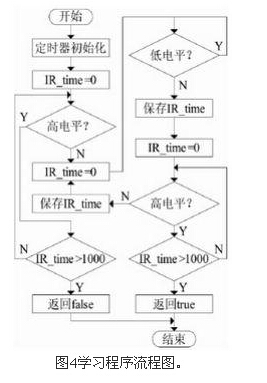
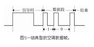
3.1 Learning function design 3.1.1 learning mode The infrared remote control has various patterns, and the coding generally includes: frame header, system code, operation code, synchronization code, frame interval code, frame tail, and the position where the synchronization code and the frame interval code appear. It is not fixed, so the pattern format is flexible and changeable. It is difficult to distinguish the coding meaning of various patterns. The encoding length of each infrared remote control is different, and the transmission methods are also various. The three most commonly used ones are: the complete frame is sent only once. The complete frame is repeatedly transmitted twice, and a complete frame is sent first, and then the frame header and one pulse are repeatedly transmitted. Faced with such a variety of coding methods, if you learn the meaning of each code, the complexity of learning will be high, and the versatility will be affected. Therefore, in order to avoid the interference of each color pattern, the system does not care about the actual meaning of the pattern data when learning, and only records the time width of the pulse. The system is mainly for an infrared remote controller with a carrier frequency of 38KHz (cycle of 26us), and uses the variable IR_time to record the received pulse width. The learning program flow is shown in Figure 4.
3.1.2 Compressed storage Because the meaning of the specific pattern data is not considered, only the width of the pulse is recorded, and the versatility of the learning function of the system is improved. However, the amount of data learned in this way is large, and the requirement for storage becomes Very high.
Although the system has designed a separate storage module for the high-capacity requirements of storage, considering the need to ensure sufficient storage capacity without increasing hardware overhead, and to meet the needs of future expansion, data compression is adopted during data storage. technology.
From the learned level data, it can be found that whether the data is 1 or 0, the level of the same duration appears, which is consistent with the characteristics of the run length coding. Run-length coding is a simple non-destructive data compression method. The advantage is that compression and decompression are very fast. The method is to calculate the continuous data length compression. For example: the data of a binary image is:
Use run-length encoding compression: 8W1B4W3B7W1B 5W.
It can be seen that the compression efficiency is extremely high and complicated encoding and decoding operations can be avoided. Therefore, during storage, the system performs run-length encoding compression on the learned data [7, 8]. For example, the data of a group of air conditioner remote controllers learned is [157 153 23 53...23 53 23 180 156 152 23 53... 53 23], as shown in Fig. 5, after using the run-length coding compression for the repeated level data, the original 199-byte air conditioner remote control code needs only 106 bytes to store, and the compression rate is 53.27%. Therefore, The storage code compression is adopted for the learned data characteristics during storage, which can effectively save storage space.
3.2 Transmitting Function Design Many of the existing infrared remote controllers use external circuits to generate carrier signals, such as the NEC555 oscillator to generate carrier signals. In order to reduce hardware overhead, the system uses a timer inside the microcontroller to generate a carrier. The system uses the Atmega16 microcontroller, its timer is powerful, with normal mode, CTC mode, fast PWM mode, phase correction PWM mode and other working modes, the system uses timer 1, so that it works in fast PWM mode, generating duty cycle It is a 1:3 38KHz PWM wave. When an instruction is sent, the MCU extracts the instruction information from the corresponding EEPROM, and then modulates it onto the generated carrier, and then transmits the infrared signal through the transmitting circuit.
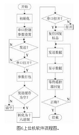
3.3 Communication function design 3.3.1 Host computer communication In addition to the manual operation of the remote controller, the remote controller can also control the remote controller through the host computer software. The remote control communicates with the host computer through the RS232 module. First configure the host computer software to determine the serial port number, select the same baud rate and master and slave device address as the device, then select the corresponding command according to the need, click send to pass the host computer. Control the device. Since the remote controller is based on the air conditioner remote control, when communicating with the host computer, the temperature detection module in the system uploads the real-time temperature, which is convenient for the user to adjust. Figure 6 is a software flow chart of the host computer.
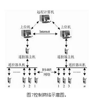
3.3.2 Network Control In order to realize networked control of multiple devices, an RS485 module is also designed. Each sub remote controller is connected through the "A" and "B" ends of the RS485 module to form a control network, as shown in Figure 7, one of which serves as the main remote controller, and communicates with the host computer through the RS232 module. When the host computer needs to control a certain sub-device, select the corresponding sub-device address number and send the command. After receiving the command information, the main remote controller sends the command to the corresponding sub-device. The PC connected to the main remote control connects to the Internet and acts as a local server for remote control.
The user logs in to the remote client and establishes a connection with the server after being authenticated. The command can be sent to the local server, and the local server performs corresponding operations on the remote controller through serial communication. If the remote control host is far away from the host computer, RS232 can not meet the communication needs, or you can use the RS232-485 adapter on the PC of the host computer, and directly connect the remote control network to the PC 485 interface through RS485. Use the host computer to directly control the remote control network.
4 Conclusion <br> This paper designed a smart air conditioner remote control. The system uses only the pulse width of the infrared signal, regardless of the infrared encoding format. The infrared encoding signal is compressed by the run length encoding algorithm and saved to the EEPROM, and the 38KHz carrier is directly generated by the PWM mode of the main control chip timer, thereby saving the economy. Hardware cost, in addition to manual operation, the remote control can be controlled by the host computer, which is convenient to use.
The system successfully realized the learning and function reproduction of various air conditioner remote controllers, with flexible operation and stable performance. The system can also be used in smart homes to control different infrared devices, and can also be used for remote network control, providing an implementation method for smart home and remote monitoring.
PRODUCT DESCRIPTION
- Just add water and essential oils
- Extremely quiet and easy to clean
- Cool mist / no heat involved / no risk of burns
- Automatically shuts off
- Runs 2 to 3 hours
- USB cord included
- Rotating LED Lights
- 1 Year Warranty
- Purify the air you breathe with this Usb Essential Oil Diffuser
- Convenient Usb Aroma Diffuser can be customized of your company name and logo
- Creates a lasting brand impression on a useful product for the home or office
- Essential Oil help soothe the mind and improve mental well-being
DITUO Solutions Usb Oil Diffuser unites aromatherapy with modern scientific innovation to create a Usb Diffuser that plugs into your laptop with a USB cable. This mobile diffuser is PP material and diffuses essential oils for up to 3 hours. It utilizes high-frequency ultrasonic electrical vibrations to create an ultra-fine mist. This diffusion method doesn't utilize heat, which maintains essential oil integrity and holistic properties every time you use it.
USB Diffuser
Usb Diffuser,Usb Essential Oil Diffuser,Usb Oil Diffuser,Usb Aroma Diffuser
Shenzhen Dituo Electronic Co.,Ltd. , https://www.sz-dituo.com