A circuit capable of amplifying a weak signal is called an amplifying circuit or an amplifier. For example, the key component in a hearing aid is an amplifier.
Use and composition of the amplifier circuit
The amplifier has an AC amplifier and a DC amplifier. The AC amplifier can be divided into low frequency, medium source and high frequency according to the frequency; the output signal strength is divided into voltage amplification, power amplification and the like. There are also amplifiers that use integrated op amps and special transistors as devices. It is the most complex and variable circuit in electronic circuits. But beginners often encounter only a few typical analog circuits.
When reading the magnifying circuit diagram, it is still carried out according to the principles and steps of “gradual decomposition, seizing key, careful analysis, and comprehensive integrationâ€. First, the entire amplifying circuit is separated step by step according to the input and output, and then the key is grasped step by step to analyze and improve the principle. The amplifying circuit has its own characteristics: First, there are two working states, static and dynamic, so sometimes it is necessary to draw its DC path and AC path for analysis; second, the circuit often adds negative feedback, and this feedback is sometimes In this level, sometimes it is feedback from the latter level to the former level, so it is necessary to be able to “see ahead†when analyzing this level. After the principle of each level is solved, the entire circuit can be connected for comprehensive synthesis.
Below we introduce several common amplification circuits.
Low frequency voltage amplifier
A low-frequency voltage amplifier is an amplifier that operates at a frequency between 20 Hz and 20 kHz and requires a certain voltage value without requiring a strong current.
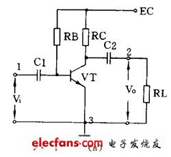
(1) Common emitter amplifying circuit
Figure 1 (a) is a common emitter amplifying circuit. C1 is the input capacitor, C2 is the output capacitor, transistor VT is the device that amplifies, RB is the base bias resistor, and RC is the collector load resistor. 1 and 3 are inputs, and 2 and 3 are outputs. The 3 end is a common point, usually grounded, also called the "ground" end. The DC path during static is shown in Figure 1 (b), and the AC path is shown in Figure 1 (c). The circuit is characterized by a voltage amplification factor from a dozen to more than one hundred. The phase of the output voltage and the input voltage are opposite, and the performance is not stable enough for general use.

Automotive Switches
Automotive Switches,ie, Car Switches are gradually enjoy a lager popularity in the Automobile industry , including Automotive Push Button Switches, Automotive Toggle Switches , Automotive Rocker Switches , Automotive Rotary Switches, Automotive Battery Switches.

Our Car Electrical Switches could equip with LED Light or without light, which is according to our customer`s requirement. Meanwhile, our Automotive Push Button Switches could reach IP 67 waterproof rating. We have different shape of Automotive Electrical Switches for you to choose, comprising Square and Round.
Our Automotive Switches is normally used to turn on the car, and it is normally use the High Current to conduct the engine.

Automotive Switches
Automotive Switches,Custom Automotive Switches,Automotive Electrical Switches,Automotive Accessory Switches
YESWITCH ELECTRONICS CO., LTD. , https://www.yeswitches.com