In the past, we occasionally mentioned I2S when discussing audio topics. I mentioned I2S in some of the previous articles, and others will mention it when doing audio research. In short, it is a synchronization method that transfers stereo data from one end to the other.
Most people think that I2S has three kinds of signals:
1. Data: input or output data
2. Bit clock (BCK): A signal that establishes the boundary between two adjacent bits in a data stream.
3. Left/Right Clock (LRCK)/Wordclock (Wordclock): A slow clock that operates at a sample rate with a 50% duty cycle that establishes between two adjacent channels (left and right) in the data stream. The border.
The behind-the-scenes hero of I2S is the master clock (MCK), also known as the system clock (SCK), which is often ignored by digital signal processor (DSP) programmers and other processor enthusiasts. The master clock (MCK/SCK) is typically a clock of 64, 128, 256, and 512 times the sample rate (FS). It can be supplied directly from an input pin or internally by some phase-locked loop (PLL).
In general, DSPs do not require an audio master clock because they can process data at a completely different rate and then drive data into the output buffer at some rate (or through input buffering) driven by BCK and LRCK. Receive data).
If you can temporarily remove your attention from your processor, you will find that the audio master clock is much more important. Most of the MCK/SCK input audio converters require clock synchronization, while others allow for out of phase. This means that they need to be provided by the same high-speed clock and then removed. Some of the customers I have contacted will tell me in a sudden inspiration: "My ADC needs an MCK, but it is too far away from my DAC. So I have to place a crystal next to each converter..." The idea can be understood, but please "Don't do this!"
When you purchase a crystal, you cannot guarantee that it is exactly 48.000 kHz. Your analog-to-digital converter (ADC) crystal may operate with an accuracy of +5%, while a digital-to-analog converter (DAC) may operate with an accuracy of –5%. This precision will have catastrophic consequences for your design! Why is this, the following will tell you.
For I2S
Master clock for audio ADC
As shown in Figure 1, a high-speed master clock (for example, a 24.576 MHz clock) is used to drive the ADC's oversampling modulator. The data from the oversampling modulator is then decomposed into the sample rate given by LRCK.
When the ADC is operating in master mode (generating BCK and LRCK as outputs), the ADC simply divides the MCK/SCK to generate the LRCK and CK signals. That's right! LRCK/BCK and the master clock are synchronized - the phase may also be synchronized (unless it is a special splitter).
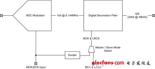
Figure 1 General ADC structure diagram
If acting as a slave and the master clock is out of sync, it will produce too much or too little data so that the digital decker cannot fit just the output word. Under these conditions, many ADCs refuse to stream data.
The same is true for DAC. Figure 2 shows an advanced DAC block diagram. Here, the interpolator needs to be operated by MCK/SCK, and the MCK/SCK also drives the Δ∑ modulator. If MCK/SCK is not an integral multiple of the sample rate (64/128/256/512), erroneous data may appear at the Δ∑ modulator output.

Figure 2 General DAC structure
Where am I/how do I generate MCK/SCK?
In today's industrial applications, CMOS oscillators are supported by many crystal oscillators and are in close proximity to these crystal oscillators. They all have very good precision and low jitter. Voltage controlled oscillators (VCOs) are occasionally used, but they are plagued by their output jitter.
Many modern audio converters now integrate a PLL to generate the MCK through slow BCK. This is very effective. However, you should be aware that there is always the possibility of jitter when using the PLL, which reduces audio performance.
In addition, I recommend that if you choose between the crystal source driving the ADC or the DAC, please choose to run the ADC through a crystal generation source. If the input is terrible, then what you do will not help! (Like you can't polish the mud!)
Therefore, the principle that my proposal follows is:
1. If the converter is an I2S slave, you must provide all three I2S clocks (MCK, BCK, and LRCK) through the same source (or the internal PLL if the converter is included).
2. If the converter is an I2S master, be sure to provide a reliable, jitter-free MCK source. Then let the converter allocate itself. When possible, let the ADC operate in master mode with a reliable low-jitter MCK source. This ensures the lowest jitter and minimum high frequency distortion.
Plate non-damaged desulfator with Smart pulse, Simple and Safe, Restore your battery when charging.
Most of Electric vehicle use lead-acid battery bank(12V /6V /8V cells packed in Series)as the power source, The design lifespan of battery is 2~3 years, but actually the battery is usually failure after 6~12 months used which State-of-capacity gradually decline and even some scraped. Through analysis by cutting a large number of failure batteries, the battery water loss and sulfation is quite prominent. Such as the phenomenon of battery sulfation and water dehydration can be effectively inhibited to prolong the service life greatly up to 2 times.
EV Battery Charging Restorer is a new generation of high-tech products developed specifically for restoring Electric vehicle battery when it is charging every time, it utilizes the energy from the charger when charging, generating electronic smart pulse with special frequency to be resonance with the thick lead sulfate crystals in battery charging process. Under the disturbance by the specific frequency pulse, the recrystallization of lead sulfate can be prevented effectively
Product features:
1. The use of advanced electronic pulse repair technology, no-damaged eliminate battery plate sulfation crystal. Recovery of battery capacity, ensure the EV driving mileage is longer.2. The connection with charger is simple, safe and convenient, and Smart Pulse Charging Restorer can be used in conjunction with the charger for each charging process. The problem of sulfation of the plate can be eliminated during every charging process.
3.It smartly identify 72V/60V/48V/36V battery bank Spec, automatically adapt to precise voltage, automatically adjust the restore electric pulse.This Battery pulse maintainer is suitable for the popular 72V~36V batteries of electric vehicles, buy a set, multi vehicles benefit in family.
4. A strict circuit filtering technique, does not repair your charger as a pulse, without changing the structure of the charger, does not affect the charging parameters of the charger, safe and carefree.
EV Battery Charging Restorer
EV Battery Charging Restorer,Electric Motorcycle Battery Restorer,EBike Power Battery Repair,Electric Cycle Battery Repair
Shenzhen Daceen Technology Co., Ltd. , https://www.daceen-sz.com