Direct upconversion is a highly cost-effective approach for designing transmitters, making it a key consideration in base station development. In WCDMA technology, the carrier-to-noise ratio (CNR) of the I/Q modulator plays a crucial role. The TRF3702 I/Q modulator excels in capacitive noise performance while maintaining strong ACPR (Adjacent Channel Power Ratio) characteristics. This paper explores the technical requirements for CNR in analog quadrature modulators used in both single-carrier and multi-carrier WCDMA base stations.
Implementing a direct upconversion architecture in a transmitter system is often preferred due to its ability to reduce complexity and component count, thus lowering overall costs. Figure 1 illustrates the block diagram of a WCDMA direct upconversion architecture. Unlike dual-conversion systems, this design eliminates the need for an IF signal generator, IF synthesizer (PLL/VCO), IF-RF mixer, and SAW filter, simplifying the signal chain significantly.
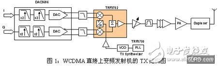
Structure diagram of WCDMA direct up-conversion architecture
The primary performance metrics for I/Q modulators in WCDMA are ACPR and noise performance at carrier offsets of 50 MHz and 60 MHz. Among these, the noise performance requirements are the most stringent. These limits are defined by spurious emission regulations, which cannot be exceeded under any circumstances (see section 6.6.3.1.2 [1]).
Spurious emission limits define the maximum allowable offset for a carrier. Key parameters include spurious emissions at 50 MHz (-25 dBm) and 60 MHz (-30 dBm), with a measurement bandwidth of 1 MHz. Table 2 provides an example of the 60 MHz offset scenario. In this case, the single carrier operates at the edge of the frequency band (either 2167.5 MHz or 2112.5 MHz). At this point, the offset of 60 MHz falls just outside the Tx band, where the duplex filter does not provide any attenuation.
Since the operating bandwidth is 60 MHz (2110–2170 MHz), direct upconversion does not use channel filters to suppress the noise floor. Therefore, the I/Q modulator must deliver excellent noise performance on its own.
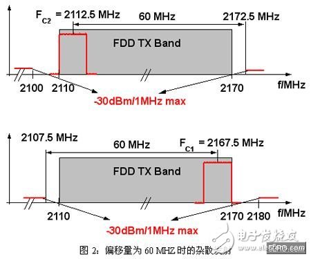
Spurious divergence at an offset of 60 MHz
A -30 dBm level represents the absolute noise level, directly influencing the CNR performance of the I/Q modulator. Based on the calculations in Table 1, the required CNR performance can be determined.
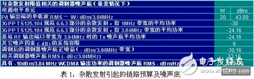
Link budget and noise ratio caused by spurious divergence
In this analysis, the output power is 43 dBm, which corresponds to the RMS power of a single WCDMA carrier (3.84 MHz measurement bandwidth). When the spurious emission is measured at -30 dBm with a 1 MHz bandwidth, this translates to -24.16 dBm at 3.84 MHz. Considering a 6 dB system tolerance, the noise floor at the PA output is -30.16 dBm. This results in a CNR of -73.16 dBc/3.84 MHz or -139 dBc/Hz. Thus, the noise floor at the I/Q modulator output should not exceed -149 dBm/Hz when the output power is -10 dBm.
In multi-carrier designs, meeting this noise requirement is generally easier because the 60 MHz offset allows for some noise reduction through the duplex filter. However, the spurious emission limit at 50 MHz is much stricter, capped at -25 dBm (1 MHz bandwidth). For 60 MHz offsets, the limit can be relaxed by 5 dB. In systems with a 15 MHz bandwidth, the 50 MHz offset becomes particularly important. As in the single-carrier case, the 50 MHz offset occurs at 2107.5 MHz or 2172.5 MHz, where the duplex filter offers no noise reduction.
ACPR Requirements
For WCDMA I/Q modulators, the importance of ACPR requirements comes second only to the CNR specifications. ACPR, known as ACLR in UMTS standards, refers to the power ratio between the main channel and adjacent channels (5 MHz offset) and phase channels (10 MHz offset). The UMTS standard requires 45 dBc for interphase channels and 50 dBc for adjacent channels. These values depend on the power amplifier output, so components in the signal chain must meet these levels to avoid degrading PA performance. Generally, I/Q modulators are expected to achieve better than 60 dBc.
Performance of the TRF3702 Combined with the DAC5686
The TRF3702 was tested in combination with the DAC5686 (a 16-bit, 500MSPS dual DAC) using a passive port configuration to demonstrate its ACPR and noise performance. The passive port setup is shown in Figure 3. For simplicity, the filtering portion of the DAC has been omitted.
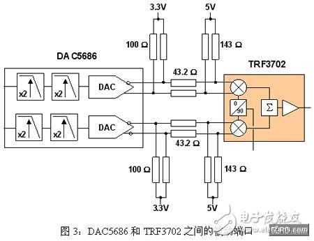
Passive port between DAC5686 and TRF3702
The DAC5686’s output error tolerance ranges from AVDD -0.5V to AVDD +0.5V, allowing for a straightforward connection to the TRF3702’s normal input voltage of 3.7V. At 50 MHz and 60 MHz offsets, the noise performance of the TRF3702 is below -144 dBc/Hz, well within the calculated requirements (including a 6 dB margin, as seen in Table 1). With an output power of -8 dBm, the ACPR performance of the TRF3702 reaches approximately 64 dBc.
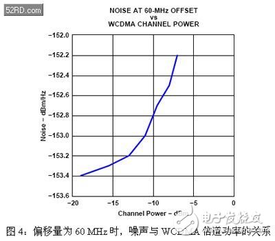
The relationship between noise and WCDMA channel power at a 60 MHz offset
This figure shows how noise relates to channel power at the TRF3702 output when offset by 60 MHz. When the output power is around -15 dBm, the calculated CNR remains low, resulting in improved ACPR performance.
At lower output powers, the ACPR of the TRF3702 can exceed 71 dBc. Figure 1 demonstrates the ACPR characteristics of a single-carrier WCDMA signal at an output power of 71.2 dBc, with the CNR still within acceptable limits.
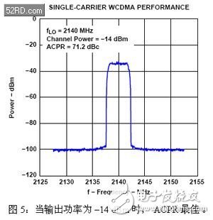
Best ACPR when the output power is -14 dBm
In conclusion, the analysis of the maximum noise floor in a direct upconversion analog modulator for WCDMA base stations shows that the TRF3702 meets all noise requirements with sufficient margin. The noise floor should not exceed -139 dBc/Hz (including a 6 dB tolerance). The noise performance of the TRF3702 connected to the DAC5686 via a passive port is around -143 dBc/Hz. At a higher output power of -8 dBm, the ACPR is 64 dBc, satisfying the specification. When the output power drops to -14 dBm, the ACPR can reach as high as 71 dBc, still within the CNR requirements.
Digital Timer Switch Sockets,Digital Timer Outlet,Plug-in Time Controller,Plug In Timers,Sockets with Timers
NINGBO COWELL ELECTRONICS & TECHNOLOGY CO., LTD , https://www.cowellsockets.com