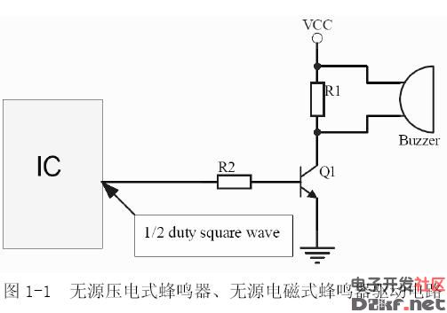
Passive buzzer drive circuit diagram
As shown in the figure below, the SH69P43 is used as the control chip, and a 4MHz crystal oscillator is used as the main oscillator. PORTC.3/T0 acts as the I/0 port to drive the buzzer LS1 through the transistor Q2.
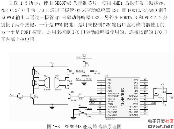
One is the PWM button, which is used to control the output port to drive the buzzer. The other is the PORT button, which is used to control the I/O port to drive the buzzer. The I/O port of the connected button is opened internally. resistance.
The sensor includes linear encoder and rotary encoder, which is used for the position measurement of speed, displacement and angle. Yuheng optics can provide rotary encoders based on optical, magnetic and gear principles, linear encoders based on optical principles and supporting products.

Custom Sensor,Clintegrity Encoder,Absolute Angle Encoder,Small Rotary Encoders
Yuheng Optics Co., Ltd.(Changchun) , https://www.yhenoptics.com