In two-wire signal and HART transmission applications, due to the ground loop problem, different ground potentials generate loop current, which introduces common mode interference, generates transmission error of 4-20 mA signal, or causes HART communication interruption, etc. The device port device will be damaged. Using an effective electrical isolation method to form a two-wire signal and HART isolation transmission application can effectively solve the above problems and improve system reliability.
Ground loop problem and ground potential difference in signal transmission
There may be many reasons for the ground loop phenomenon in the meter circuit. When the signal transmission and receiving devices are connected to different grounding points or different power sources, a ground loop will occur, which is common in long-distance cable transmission. They may also be due to physical contact between the metal casing of the device and the ground. The ground loop produced an unobserved electrical circuit and an error source emerged.
Since the accuracy of the signal cannot be measured by simple observation at the receiving end of the signal, the ground loop generated by the different ground potentials introduces an undetectable error into the signal loop.
In two-wire signal transmission without signal isolation, there are signal error problems caused by these ground loops.
In some cases, signals such as lightning and surges are loaded on the signal line with long lines, damaging the modulation or detection devices on the port.
In the other case, the ground potential of the port reference of the two devices is different, which may cause the port voltage to exceed the standard and damage the device port.
Non-isolated two-wire signal transmission
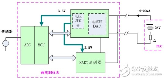
figure 1
In the circuit of Figure 1, the signal of the sensor is converted into a digital signal by the ADC, and then sent to the current loop DAC and HART modulator through the MCU to form a 4-20 mA signal output. The current loop DAC is taken from the 4-20 mA bus output of the PLC. The power supply, through the built-in voltage regulator output 3.3V and 2.5V, provides a small amount of power to the MCU and HART modulator.
In this transmission mode of Figure 1, there is a potential difference between the two-wire meter and the grounding potential of the remote PLC, which introduces common mode interference, which causes the transmission error of the 4-20 mA signal and also affects the normal communication of the HART bus. If the common mode interference is too large (beyond the allowable range of the common-mode voltage of the internal device), even the device inside the two-wire meter is damaged.
Isolated two-wire signal transmission
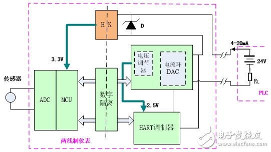
figure 2
Battery Operated Led,LED Lighted Lantern,Led Swirling Lighting
XINGYONG XMAS OPTICAL (DONGGUAN ) CO., LTD , https://www.xingyongxmas.com