Abstract: With the development of social life, people's requirements for printing and dyeing products are becoming higher and higher, especially for cloth and packaging shells, so the requirements for modern printing and dyeing technology are also increasing. With the increase of technology, it is not a small challenge to printing and dyeing equipment. The most important thing here is the synchronization control of multiple motors in large-scale printing and dyeing combined machines.
Keywords: RFID sensor tension sensor controller unit controller
In the printing and dyeing equipment, the synchronous control of the motor is mainly decided by three aspects: one is the processing speed of the tension sensor data by the processor, and the response speed of the motor to the tension sensor; the second is the difference in mechanical properties between different motor groups and their The problem of real-time simultaneous control; the third is the communication problem between the control unit and each motor group, including rate, anti-interference, etc. The traditional printing and dyeing combined machine adopts a single-chip computer plus AD / DA chip for data processing and execution. There is also a method of using DSP and single-chip computer to improve the data processing capability. With the development of the present technology, the design method of the sub-total system based on the ARM-based CORTEX-M3 core processor and CAN bus is studied.
The main controller and unit controller adopt the STM32F103 chip based on the Cortex-M3 core of ARM company introduced by ST to try a new design. This design reduces the cost on the basis of improving the system performance and realizes the docking problem with the existing printing and dyeing equipment.
1 System design
1.1 System structure design
According to the specific situation of the existing printing and dyeing combined machine in the printing and dyeing industry, the control system is mainly improved.
In the design of large-scale printing and dyeing combined machines, the main consideration is the problem of synchronous control of multiple motors. It is necessary to ensure that the cloth is stable during the transmission process. The folds of the cloth cannot be caused by insufficient tension. In the large-scale printing and dyeing combined machine, according to the complexity and simplicity of the process, the motors to be synchronized range from 8 to more than 40. The use of the CAN bus network ensures the number of independent expansion unit controllers that can be different according to the process. The system design block diagram is shown in Figure 1.
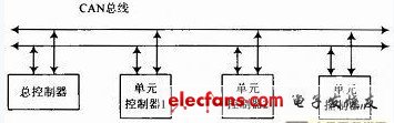
Figure 1 Block diagram of system design
1.2 The composition of the system
The system is mainly composed of main controller, unit controller, CAN bus network, and frequency converter.
The main controller is the main control unit of the system. Its main function is to display and control the working status of the entire system, as well as to set and adjust the total working parameters of the system, such as cloth speed and the sensitivity of the tension sensor. Coordinate the working state controlled by each unit.
The function of the unit controller is to fine-tune the sensitivity of the tension sensor, monitor the data of each tension sensor in real time, adjust the output voltage according to the data of each tension sensor to adjust the working state of the corresponding motor, and also respond to unexpected conditions, such as tension sensor failure And the stalling of the motor.
1.3 The specific design of the unit controller
In the design, I used the ARM-based CORTEX-M3 core chip-STM32f103RCT6 shown in Figure 2. Its features are: STM32F103 series microprocessor is the first 32-bit standard RISC (reduced instruction set) processor based on ARMv 7-M architecture, providing high code efficiency; operating frequency is 72MHz, and built-in FLASH up to 256KB Memory and 48KB of SRAM.
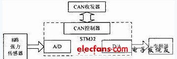
Figure 2 Design of the main part of the unit controller
It internally integrates 12-bit A / D and dual-channel 12-bit D / A, as well as a controller area network (CAN) specifically for industrial control, which provides compatible specifications 2.0A and 2.0B (active) , The bit rate is up to 1 Mb / s. It can receive and send standard frames with 11-bit identifiers, as well as extended frames with 29-bit identifiers. With 3 sending mailboxes and 2 receiving FIFOs, 3 levels and 14 adjustable filters.
1. 4 CAN bus interface design
Because the logic of the CAN bus controller of STM32 uses LVTTL, the CAN bus transceiver SN65HVD230 produced by Texas Instruments is used. SN65HVD230 can be used in higher interference environments. It uses differential reception and has the ability to withstand a wide range of common-mode interference and electromagnetic interference. The isolation circuit composed of 6N137, so that the electrical isolation of each node on the CAN bus can be well achieved. Although adding an isolation circuit increases the complexity of the node, it improves the stability and security of the node. In addition, in order to avoid signal reflection, the reliability and anti-interference ability of communication are reduced, and even communication is impossible. Therefore, two 120Ω bus impedance matching resistors need to be added at both ends of the CAN bus. The CAN interface design is shown in Figure 3.
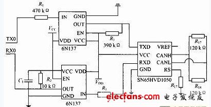
Figure 3 The specific design of the CAN bus interface
RFI Filter,Special Uses EMI Filter,Dc Inverter Filters,Low Pass EMI Filter
Jinan Filtemc Electronic Equipment Co., Ltd. , https://www.chinaemifilter.com