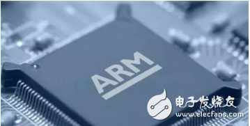
Start with a minimal system board: If you're new to ARM development, it's wise not to rush into complex designs. Focus on building a solid foundation by mastering the basics. Unlike DSPs or microcontrollers, ARM has a different startup mechanism, and you might face various issues during the process. It’s recommended to begin with a minimal system that includes only Flash, SRAM or SDRAM, the CPU, JTAG interface, and reset signals. Leave the expansion interfaces for later. A minimal system can run smoothly, giving you a head start in your project. Fortunately, most ARM peripheral interfaces are standardized, so having some hardware wiring experience will be very helpful.
Write the startup code
Develop a small piece of code that can boot up based on the hardware address. This should include port initialization, interrupt masking, copying the program to SRAM, remapping the code, setting up the interrupt handler, and linking to the C entry point. Some sample programs may contain a bootloader with many features, but don’t get overwhelmed by them—these are part of the board design and not directly related to the ARM core itself.
Study the chip datasheets
While ARM cores are compatible, each chip has unique characteristics that must be considered when writing code. Don't rely on others' samples blindly; this often leads to confusion. Understanding the chip's specifications is essential for proper implementation.
Understand operating system code
There are plenty of open-source projects available for ARM, such as Linux and uC/OS-II. If you want to improve your skills, studying these codebases is highly beneficial. They provide real-world examples of how embedded systems operate and are structured.
Hardware considerations
If you're designing the hardware yourself, most manufacturers provide demo board schematics for their chips. Studying these schematics helps you understand how resources are allocated. The device's datasheet should be thoroughly understood before proceeding with any design.

Minimum system board
Many people wonder whether a two-layer or four-layer board is better for a minimal system. For AT91, a two-layer board is acceptable, but for other chips, a four-layer board is generally recommended. For chips like 44B0, even a two-layer board can work if ground and power planes are properly handled. However, for high-speed digital circuits, a four-layer board is preferred because it allows better control over trace impedance. A 33-ohm resistor is often used at the driver end for impedance matching. At high frequencies, signal traces on PCBs behave like transmission lines, and improper impedance matching can cause signal reflections, leading to interference or circuit failure.
In a four-layer board, the outer layers are typically used for signal routing, while the inner layers serve as power and ground planes. This setup helps reduce crosstalk and provides a more stable reference plane. The characteristic impedance of a transmission line depends on factors like trace width, distance from the reference plane, copper thickness, and dielectric material. Calculating these values is possible using standard formulas, and many tools are available for this purpose.
While two-layer boards can be used for low-speed designs, they lack the ability to control impedance effectively. Impedance matching is crucial in high-speed circuits, and resistors like 33 ohms are often placed in series at the driver end to match the output impedance with the line impedance, reducing reflections. At the receiving end, parallel resistors can also be used, though this is less common in digital systems due to complexity and multiple receivers.
High frequency isn't just about clock speed—it's also about signal rise and fall times. A fast edge time implies higher frequency components in the signal. For example, a 1 ns rise time corresponds to a bandwidth of around 500 MHz. This means that even a relatively slow system might need careful PCB layout and impedance control.
Sometimes, designers intentionally slow down edge rates to avoid signal integrity issues. Many high-speed ICs allow adjustment of output slope. Linux offers a complete toolchain, making it easy to build embedded environments and cross-compilation setups. It also reduces the need for expensive simulation tools like ICE. The open nature of the Linux kernel allows for true hard real-time systems and supports soft real-time applications. With its strong networking capabilities, Linux can easily support an embedded TCP/IP stack.
A basic embedded Linux system requires three main components: a boot tool, a minimal Linux kernel (with memory management, process management, and scheduling), and an initialization process. To make it functional and scalable, you may also need hardware drivers, applications, a file system (in ROM or RAM), and possibly a TCP/IP stack.
Taixing Longyi Terminals Co.,Ltd. , https://www.txlyterminals.com