Each instrument has its own unique communication protocol, such as modbus communication protocol, RS-232 communication protocol, RS-485 communication protocol, HART communication protocol, etc., then how do these communication protocols work, what are the advantages and disadvantages? What? This article will focus on several common communication protocols!
Communication protocol: Also known as communication protocol, it refers to an agreement between the two parties on data transmission control. The agreement includes uniform definition of data format, synchronization mode, transmission speed, transmission step, error detection mode and control character definition. The two parties must comply with each other. It is also called link control procedure.
Commonly used instrument communication protocols :· Modbus communication protocol
· RS-232 communication protocol
· RS-485 communication protocol
· HART communication protocol.
· MPI communication
· Serial communication
· PROFIBUS communication
· Industrial Ethernet
· ASI Communication
· PPI communication
· Remote wireless communication
· TCP
· UDP
· S7
· profibus
· pofinet
· MPI
· PPI
· Profibus-DP
· Devicenet
· Ethernet
Modbus communication protocol 1The Modbus protocol was originally developed by Modicon. At the end of 1979, the company became part of Schneider Automation, and Modbus is now the world's most popular protocol in the industry. This protocol supports legacy RS-232, RS-422, RS-485, and Ethernet devices.
Since the modbus protocol is completely transparent and the required hardware and software is very simple, it makes it a common industry standard. Many industrial equipment, including PLCs, DCS, smart meters, etc., use the Modbus protocol as the communication standard between them. With it, control equipment produced by different manufacturers can be connected into an industrial network for centralized monitoring.
CharacteristicsThe Modbus protocol is a versatile language applied to electronic controllers. Through this protocol, controllers can communicate with each other and between controllers via a network (such as Ethernet) and other devices. It has become a common industry standard. This protocol defines a message structure that a controller can recognize, regardless of the network through which they communicate.
The modbus communication protocol is a master-slave asynchronous half-duplex communication protocol. It adopts a master-slave communication structure, which enables one master station to perform two-way communication for multiple slave stations. It describes how a controller requests access to other devices, how to respond to requests from other devices, and how to detect errors and record them. It develops a common format for message domain patterns and content.
The Modbus protocol includes ASCII, RTU and other communication methods, and does not specify the physical layer. This protocol defines the message structures that the controller can recognize and use, regardless of the network through which they communicate. The standard Modicon controller implements serial Modbus using RS232C. The ASCII and RTU protocols of Modbus stipulate the structure of the message, the data, the command and the answering method. The data communication adopts the master-slave mode, and the master station sends a data request message. After receiving the correct message, the slave station can send data to the master station. In response to the request; the primary station can also directly send a message to modify the data of the slave to achieve two-way read and write.
Master/slave principle
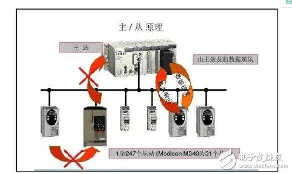
When communicating on a Modbus network, this protocol determines that each controller needs to know their device address, identify messages sent by address, and decide what action to take. If a response is required, the controller will generate feedback and send it out using the Modbus protocol. On other networks, messages containing the Modbus protocol are converted to frame or packet structures used on this network. This conversion also extends the method of solving the section address, routing path, and error detection based on the specific network.
When communicating over a network, the Modbus protocol determines that each controller needs to know their device address, identify messages sent by address, and decide what action to take. If a response is required, the controller will generate a response and send it to the interrogator using the Modbus protocol.
The Modbus protocol needs to verify the data. In addition to parity in the serial protocol, the ASCII mode uses LRC check, and the RTU mode uses 16-bit CRC check. In addition, Modbus uses the master-slave mode to send and receive data periodically. In actual use, if a slave station is disconnected (such as a fault or shutdown), the master can diagnose it, and when the fault is repaired, the network can be automatically turned on. Therefore, the reliability of the Modbus protocol is better.
Modbus and OSI reference model 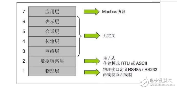
Modbus ASCII communication method 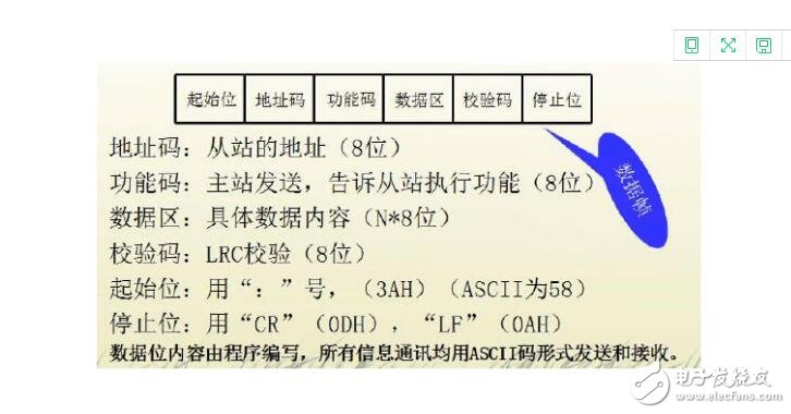
Data Frame 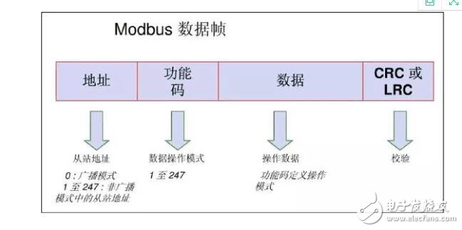
Broadcast mode (for write operations only) 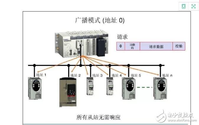
Non-broadcast mode 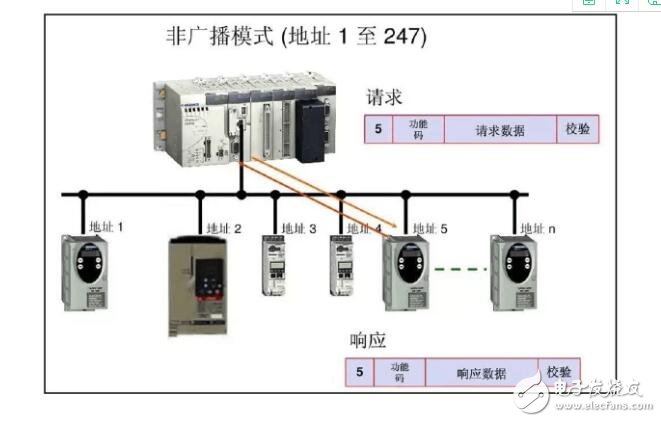
Modbus RTU communication method 
RS-232 is a serial physical interface standard developed by EIA (Electronic Industry AssociaTIon). RS is an abbreviation of the English "recommendation standard", 232 is the identification number usually. The RS-232 interface is available in 9-pin (DB-9) or 25-pin (DB-25) versions. There are two sets of RS-232 interfaces on a personal computer, called COM1 and COM2.
RS-232 interface
The RS-232 standard has two signal lines and nine signal lines, including one main channel and one auxiliary channel. In most cases, the main channel is mainly used. For general duplex communication, only a few signal lines are needed, such as one transmission line, one reception line, and one ground line.
Transmission rateThe data transmission rates specified by the RS-232 standard are 50, 75, 100, 150, 300, 600, 1200, 2400, 4800, 9600, 19200 baud.
Remote communication connection data terminal
The RS-232 standard was originally developed as a telecommunications connection data terminal equipment (DTE) data communication equipment (DCE). Therefore, the development of this standard does not consider the application requirements of computer systems. But now it is widely borrowed for the near-end connection standard between computers (more precisely, computer interfaces) and terminals or peripherals. Obviously, some of the provisions of this standard are inconsistent and even contradictory with computer systems. With this understanding of the background, it is not difficult to understand where the RS-232C standard is incompatible with the computer.
"send" and "receive"The "send" and "receive" mentioned in the RS-232 standard are all based on the DTE position, rather than standing in the position of the DCE. In computer systems, where information is often transferred between the CPU and the I/O device, both are DTEs, so both parties can send and receive.
Electrical characteristicsThe EIA-RS-232 specifies electrical characteristics, logic levels, and various signal line functions.
On TxD and RxD:
Logic 1 (MARK) = -3V ~ -15V
Logic 0 (SPACE) = +3 ~ +15V
On control lines such as RTS, CTS, DSR, DTR and DCD:
Signal valid (on, ON state, positive voltage) = +3V ~ +15V
Invalid signal (open, OFF state, negative voltage) = -3V to -15V
RS-232 interface definition (9 cores) 
1 frequency grounding
2 Send data TXD
3 receiving data RXD
4 request to send RTS
5 allowed to send CTS
6 Data ready for DSR
7 signal ground SG
8 carrier detection DCD
9 send back (+)
10 undefined
11 data transmission (-)
12~17 undefined
18 data reception (+)
19 undefined
20 data terminal ready for DTR
21 undefined
22 Ringing RI
23~24 undefined
25 Receive return (-)
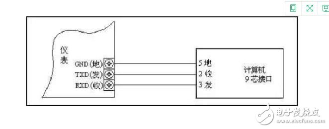
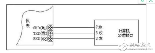
RS-232 serial communication wiring method (three-wire system)
As long as the serial port transmits data, it can be realized by receiving data pins and sending pins: the receiving pin and the sending pin of the same serial port are directly connected by wires, and the two serial ports are connected or one serial port is connected with multiple serial ports. The receiving data pins (or lines) are connected to the transmitting data pins (or lines) and cross each other, and the signal grounds are correspondingly connected.
9-pin D-type serial port: 2 "RXD", 3 "TXD", 5 "logic ground".
25-pin serial communication wiring method
(1) The signal level of the interface is high, which is easy to damage the chip of the interface circuit. Because it is not compatible with the TTL level, it needs to use the level conversion circuit to connect with the TTL circuit.
(2) The transmission rate is low, and the baud rate is ≤ 20 Kbps in asynchronous transmission.
(3) The interface uses a signal line and a signal return line to form a common ground transmission form. This common ground transmission is prone to common mode interference, so the noise immunity is weak.
(4) The transmission distance is limited, and the maximum transmission distance standard value is 50 feet (actually ≤ 15 meters).
RS-485 communication protocol 3The RS-485 standard is developed on the basis of RS232, which increases the multi-point and two-way communication capability, that is, allows multiple transmitters to be connected to the same bus, and increases the driver's driving capability and collision protection characteristics. The bus common mode range is named after the TIA/EIA-485-A standard.
Electrical characteristics of RS-485:The logic "1" is represented by a voltage difference between the two lines of +(2-6)V; the logic "0" is represented by a voltage difference between the two lines of -(2-6)V. The interface signal level is lower than RS-232, and it is not easy to damage the chip of the interface circuit, and the level is compatible with the TTL level, which is convenient for connection with the TTL circuit.
Propagation rate:RS-485 data has a maximum transfer rate of 10Mbps
RS-485 interface:It is a combination of balanced driver and differential receiver, which has enhanced anti-common-mode interference capability, that is, good anti-noise interference.
Baud rate:1200bps, 2400bps, 4800bps, 9600bps, 19200bps, 38400bps, 125K
Communication interface mode:RS485 interface: asynchronous, half-duplex, serial
Data Format:1 start bit, 8 data bits, 1 stop bit, no parity
1 start bit, 8 data bits, 1 stop bit, odd parity
1 start bit, 8 data bits, 1 stop bit, even parity
The default data format is used when connecting to the fieldbus adapter PROFIBUS.
The maximum transmission distance of the RS-485 interface is 4000 feet, which is actually up to 3000 meters (the theoretical data, in practice, the limit distance is only about 1200 meters), and the RS-232-C interface is on the bus. Only one transceiver is allowed, which is a single station capability. The RS-485 interface allows up to 128 transceivers to be connected on the bus. That is, it has multi-station capability, so users can easily establish a device network with a single RS-485 interface.
9-pin type interface:RS485 interface signal meaning
3 RXD- Receive data
4 RXD+ receiving data
5 TXD+ send data
7 TXD- send data
Disadvantages:In many cases, when connecting an RS-485 communication link, simply connect the "A" and "B" ends of each interface with a pair of twisted pairs. While ignoring the connection of the signal ground, this connection method can work normally in many occasions, but it has buried a large hidden danger common mode interference problem: the RS-485 interface uses differential transmission mode, and does not need to To detect a signal at a reference point, the system only needs to detect the potential difference between the two lines. However, people often overlook that the transceiver has a certain common-mode voltage range. The common-mode voltage range of the RS-485 transceiver is -7~+12V. Only when the above conditions are met, the entire network can work normally. When the common mode voltage in the network line exceeds this range, it will affect the stability and reliability of the communication, and even damage the interface.
HART Protocol 4HART (Highway Addressable Remote Transducer), an open communication protocol for addressable remote sensor high-speed channel, is a communication protocol between the field smart meter and control room equipment introduced by ROSEMOUNT in the United States in 1985. HART devices provide communication with relatively low bandwidth and moderate response time. After more than 10 years of development, HART technology has matured abroad and has become the industry standard for smart meters worldwide.
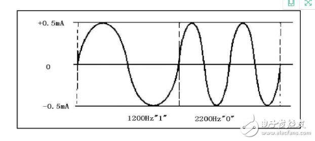
The HART protocol uses the FSK frequency shift keying signal based on the Bell202 standard, and superimposes the audio digital signal with the amplitude of 0.5 mA on the low frequency 4-20 mA analog signal for two-way digital communication, and the data transmission rate is 1.2 Mbps. Since the average value of the FSK signal is 0, it does not affect the size of the analog signal transmitted to the control system, ensuring compatibility with existing analog systems. The main variables and control information in the HART protocol communication are transmitted by 4-20 mA. Additional measurements, process parameters, device configuration, calibration, diagnostic information are accessed via the HART protocol if required.
Basic situation of the agreement· 4~20mA analog signal + digital control signal (FSK technology)
· Supports twisted pair full digital communication, which can form 15 station networks
· Support OSI open architecture, 1, 2, 7, layer
Communication model: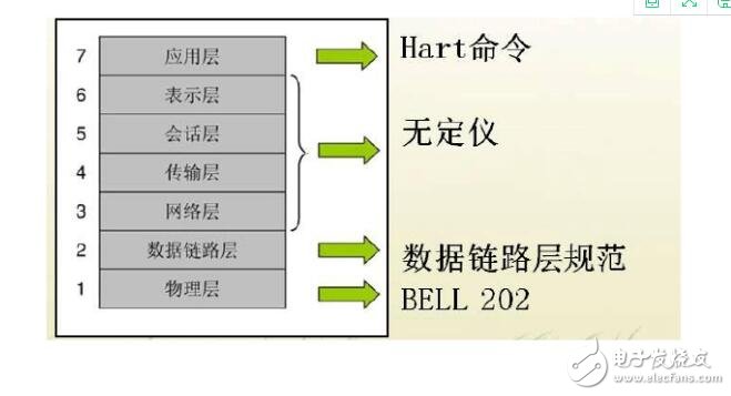
Based on the FSB technology of the Bell 202 communication standard, the basic content:
Baud rate 1200bps (slower speed)
Logic 1 1200HZ
Logic 0 2400HZ
data link layer
way of communication:1) Master-slave communication
Controlling the transmission of data frames by the master device
Allow up to 15 slave devices to connect to a multipoint communication line
2) Burst mode
Repeated transmission of data frames from the device timing
3) Half-duplex communication method
Addressing range: 0 ~ 15
When the address is 0, the 4~20mADC is in a state compatible with digital communication.
When the address is 1~15, it is in the state of full digital communication.
Specifies the structure of the communication data, each character consists of 11 bits:
1bit start bit + 8bit data + 1bit parity bit + 1bit stop bit
Application layer:
General order:· Commands applicable to all HART-compliant field devices. Includes the following:
· Read the range, unit and damping time constant of the transmitter;
· Read the number of sensors connected in series and their line system;
· Read out the manufacturer and product model;
· Read the main variables and units;
· Output current output and percentage output;
· Read and write 8-character signage, 16-character description content, date, etc.
General commands apply to most HART-compliant products, but there may be minor differences between HART products from different companies, such as writing host variable units, fine-tuning DA's zeros and gains, etc.:
· Write the damping time constant;
· Write to the transmitter range;
· Calibration (set zero and span);
· Fine-tuning the main variable zero point;
· fine tune the zero and gain of the DAC;
· Complete self-test and host reset;
Special order:Only available for a specific field device. This is a unique command of each company's products, not compatible with each other, such as characterization, fine-tuning sensor head correction. :
· Read or write the open small flow cutoff value;
· start, stop or clear the accumulator;
· Select the host variable (mass flow or density);
· Read or write configuration information;
· Calibration of the fine-tuning sensor;
HART communication mode:
The first type of "question and answer": 2 times / sec, suitable for point-to-point, multi-station connection
The second "group mode": 3.7 times / sec, only for point-to-point connections
Advantages of the HART protocol:
· Analog signals with process control information, digital signals allow two-way communication;
· (Intelligent field instrument + analog instrument, recorder and controller) hybrid system;
· Support multi-master digital communication, save wires and reduce installation costs;
· Connect the meter by renting a telephone line so that remote field instruments use relatively inexpensive interface equipment;
· Allow "question-and-answer" and "group mode" communication methods;
· The message structure is flexible, standardized, and can carry 4 process variables in one communication.
There are usually three ways to apply HART communication:
· The most common is to communicate with field smart meters using a handheld communication terminal (HHT).
· Control room instrument with HART communication function, can communicate and configure with multiple HART instruments.
· The third way is to communicate with a PC or DCS operator station.
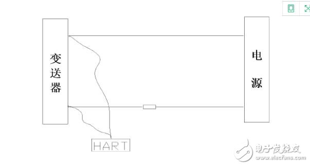
The interconnection between the smart transmitter and the HART protocol communicator needs to follow the sum of the load resistances between 250 and 600 Ω. Too small to communicate, too large for the transmitter to work. In practice, at least one standard resistor of 250 Ω or more must be connected in series in the calibration room. However, if the system basically meets the load resistance requirements in the field, the HART communicator can be directly connected to the control terminal. As shown in Figure 1
Due to the compatibility of HART instruments with the original 4-20 mA standard instruments, the development and application of HART instruments has developed rapidly, especially in equipment retrofits. Compared with FF and other protocols, the HART protocol is relatively simple, and due to the slow speed and low power consumption requirements, the data link layer and the application layer are generally implemented by software. The physical layer applies the original Bell-202 modem. To address the interchangeability and interoperability of devices from different vendors, HART uses Device Description Language (DDL).
SMC Board To Board Connector Section.
Compact high density design
Design of super reliable double beam contact
High speed signal transmission rate up to 3 Gbit / S
Polarization to ensure accurate connection
Locating pin for PCB placement
Welded bracket for secure PCB
Wide operating temperature range
Height range of non matching stack
For full automation board components
SMC Board To Board Connector Section
ShenZhen Antenk Electronics Co,Ltd , https://www.antenkwire.com