The six rectifying elements can form a three-phase full-wave rectifying circuit according to a fixed connection.
Its role is to rectify the alternating current into direct current.
Three-phase full-wave rectifier circuits are commonly used in electroplating devices, electrolysis devices, DC welding machines, charging devices, and the like. The rectifier bridge is to seal several rectifier tubes in one shell to form a complete rectifier circuit. A three-phase rectifier circuit is proposed when power is further increased or multiphase rectification is required for other reasons. The three-phase rectifier bridge is divided into three-phase full-wave rectifier bridge (full bridge) and three-phase half-wave rectifier bridge (half bridge). Select the rectifier bridge to consider the rectifier circuit and operating voltage. A rectifier circuit that requires a high output voltage requires a capacitor, and a capacitor of a rectifier circuit that does not require a high output voltage can be mounted or not. According to the frequency of the three-phase alternating current, the period is two phases in the upper half and the first phase in the lower half. The three-phase bridge rectification is to turn on the diode (positive) of the upper half of each alternating current cycle. One diode (positive) is turned on in half a cycle to obtain a full-wave (6 diodes) rectified output DC that can be turned on in both the upper and lower waveforms in a frequency cycle.
Characteristics of three-phase full-wave rectifier circuit and its working principle: main circuitThe schematic diagram is shown in Figure 1.
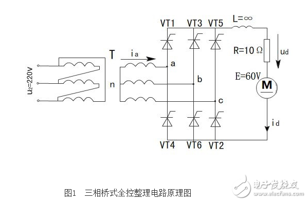
It is customary to refer to the three thyristors (VT1, VT3, VT5) in which the cathodes are connected together as a common cathode group; the three thyristors (VT4, VT6, VT2) to which the anodes are connected together are called a common anode group. In addition, it is customary to turn on the thyristors in order from 1 to 6. For this purpose, the thyristors are numbered in the order shown, that is, the three thyristors in the common cathode group that are connected to the three-phase power supply of a, b, and c are respectively VT1. VT3, VT5, and the three thyristors connected to the three-phase power supply of a, b, and c in the common anode group are VT4, VT6, and VT2, respectively. As will be understood from the later analysis, according to this number, the conduction sequence of the thyristor is VT1-VT2-VT3-VT4-VT5-VT6.
Main circuit principle descriptionThe load of the rectifier circuit is a resistive load with a back electromotive force. Assume that the thyristor in the circuit is replaced by a diode, which is equivalent to the case where the thyristor firing angle α=0o. At this time, for the three thyristors of the common cathode group, the one with the highest AC voltage value connected to the anode is turned on. For the three thyristors of the common anode group, the conduction is the lowest (or the most negative) of the AC voltage. Thus, at any time, one thyristor in the common anode group and the common cathode group is in an on state, and the voltage applied to the load is a certain line voltage. At this point, the circuit operation waveform is shown in Figure 2.
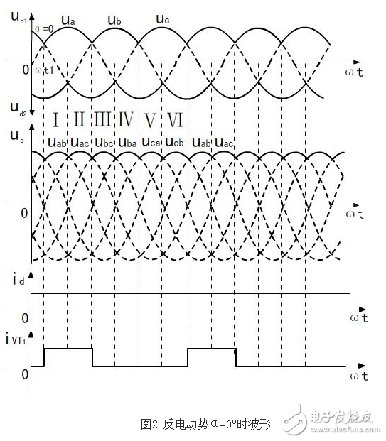
When α=0o, each thyristor is commutated at the natural commutation point. It can be seen from the corresponding relationship between the phase voltage of the two windings of the transformer and the waveform of the line voltage that each natural commutation point is the intersection of the phase voltage and the intersection of the line voltages. When analyzing the waveform of the ud, it can be analyzed from the phase voltage waveform or the line voltage waveform. From the phase voltage waveform, taking the midpoint n of the secondary side of the transformer as the reference point, when the common cathode group thyristor is turned on, the rectified output voltage ud1 is the envelope of the phase voltage in the positive half cycle; when the common anode group is turned on, the rectification The output voltage ud2 is the envelope of the phase voltage in the negative half cycle. The total rectified output voltage ud = ud1-ud2 is the difference between the two envelopes, which corresponds to the line voltage waveform, that is, the line voltage is positive. Half-week envelope.
Directly from the line voltage waveform, due to the maximum (positively the most) phase voltage of the thyristor in the common cathode group, the thyristor in the common anode group corresponds to the smallest (negatively most) phase. The voltage, the output rectified voltage ud is the subtraction of the two phase voltages, and is the largest one of the line voltages, so the output rectified voltage ud waveform is the envelope of the line voltage in the positive half cycle.
Since the load is connected to the inductor and the resistance of the inductor tends to infinity, the inductor has a resistance to current changes. When the current flowing through the inductive device changes, an induced electromotive force Li is generated at both ends thereof, and its polarity prevents the current from changing. When the current increases, its polarity prevents the current from increasing, and when the current decreases, its polarity in turn prevents the current from decreasing. This action of the inductor causes the current waveform to become flat and tends to a straight line when the inductance is infinite.
In order to explain the operation of each thyristor, one cycle of the waveform is equally divided into six segments, each segment being 60o. As shown in Fig. 2, the conduction thyristor and the output rectification voltage in each segment are as shown in the table. It can be seen from the table that the conduction sequence of the six thyristors is VT1-VT2-VT3-VT4-VT5-VT6.
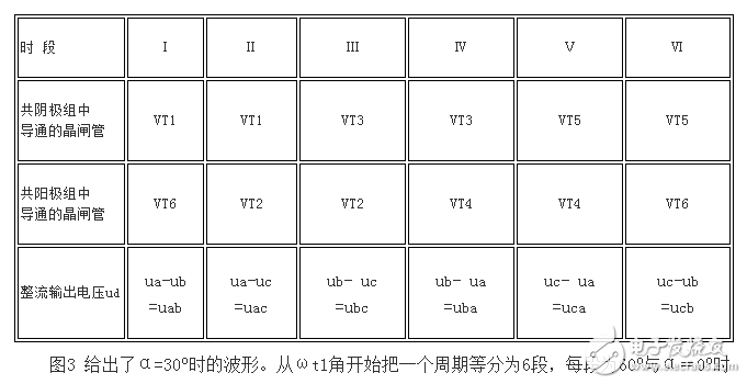
Figure 3 shows the waveform at α = 30o. Starting from the angle ωt1, divide a cycle into 6 segments. When each segment is 60o and α=0o, the ud waveform is still composed of 6-segment line voltage in one cycle, and the number of each turn-on thyristor is still the same. The law of Table 1. The difference is that the initial turn-on time of the thyristor is delayed by 30o, and the voltage of each line constituting ud is delayed by 30o, and the average value of ud is lowered. The thyristor voltage waveform also changes accordingly as shown. The figure also shows the waveform of the a-phase current ia on the secondary side of the transformer. The characteristic of this waveform is that ia is positive during the 120o state of VT1 in the on state. Due to the large inductance, the shape of the ia waveform is approximately a straight line. During the 120o period when VT4 is in the on state, the shape of the ia waveform is also approximately a straight line, but it is a negative value.
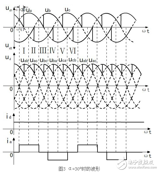
It can be seen from the above analysis that when α≤60o, the ud waveforms are continuous. For the back electromotive force with large inductance, the id waveform is a smooth straight line due to the effect of the inductance and is also continuous. When α>60o, if α=90o, the working waveform under the resistance load is as shown in Fig. 4. The average value of ud continues to decrease. Because the presence of inductance delays the turn-off time of VT, the value of ud has a negative value. When the inductance is large enough, the positive and negative areas in ud are substantially equal, and the ud average is approximately zero. This shows that the phase shift range of the α angle of the three-phase bridge full-controlled rectifier circuit with resistive back EMF is 90 degrees.
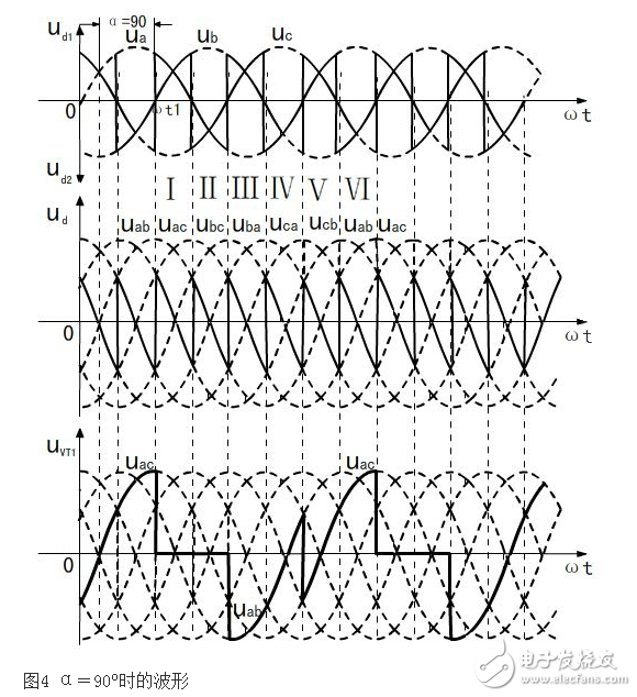
Figure 4 Waveform at α=90o
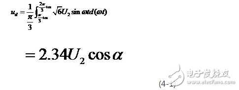
Calculation of each parameter Calculation of output valueIn the three-phase bridge type full-controlled rectifier circuit, the waveform of the rectified output voltage pulsates 6 times in one cycle, and the waveform of each pulsation is the same, so when calculating the average value, only one pulse wave (ie 1/6) is needed. Cycle) can be calculated. In addition, since the voltage output waveform is continuous, the zero-crossing point of the line voltage is the zero point of the time coordinate, and the average value when the rectified output voltage is continuous can be obtained.
The output waveform at the time is shown in Figure 11.
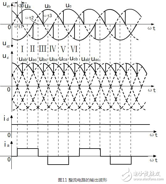
As shown in FIG. 11, one cycle is equally divided into six parts from the time of ωt1, and the thyristor of the common cathode group VT1 receives the trigger signal at the time of Wt1, and the cathode output voltage Ud1 is the phase a phase voltage having the largest amplitude; At the time of Wt2, the next trigger pulse arrives. At this time, the output voltage of phase a decreases, and the output voltage of phase b rises, so that the cathode output voltage becomes the b phase phase voltage. When the third pulse arrives at Wt3, the thyristor VT1 turns off and the thyristor turns off. VT2 is turned on, and the output voltage is the highest phase f phase voltage at this time; the above steps are repeated, that is, the common cathode group output voltage Ud1 is the envelope in the positive half cycle.
The output waveform principle in the common anode group is the same as that of the common cathode group, except that each trigger pulse is 180 degrees out of phase with the pulse in the cathode group. The turn-on sequence of the six periods is as shown in Table 1, except that Wt1 is delayed by 30 degrees from zero. Thus, the final output rectified voltage is the difference between the output voltage of the common cathode group and the output voltage of the common anode group.
Due to the large inductance L in the circuit, the output current is a nearly smooth straight line. The figure also shows the waveform of the a-phase current ia on the secondary side of the transformer. The characteristic of this waveform is that ia is positive during the 120o state of VT1 in the on state. Due to the large inductance, the shape of the ia waveform is approximately a straight line. During the 120o period when VT4 is in the on state, the shape of the ia waveform is also approximately a straight line, but it is a negative value.
InverterThe schematic diagram of the inverter is shown in Figure 12.
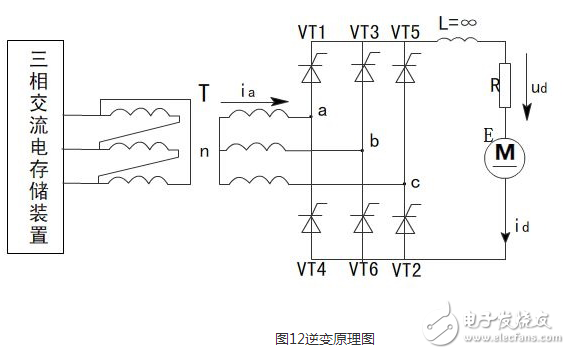
As shown in FIG. 12, when the motor M is in operation, the trigger angle α of the regulating rectifier circuit is adjusted to α “90°. At this time, the rectifier circuit operates in the rectification state, and the three-phase AC point storage device supplies power to the M to operate the M in the electric state. The conversion of electrical energy into kinetic energy drives the car.
When the motor M has excess energy, adjust the α angle so that α “90°, so that the average value of the output DC voltage Ud is negative, and |Em|â€|Ud|, when the rectifier circuit works in the inverter state, the excess of the motor M The energy is exchanged for electrical energy, M delivers current to the three-phase alternating current storage device, and the three-phase alternating current storage device receives and stores electrical energy.
480W Medical Power Supply,480W Medical Device Power Supply,480W Medical Power Adapter,480W Rade Power Supplies
Shenzhen Longxc Power Supply Co., Ltd , https://www.longxcpower.com