Digital video processing technology improves image quality and monitoring efficiency, making the system easy to manage and maintain. The entire system is a modular structure, small in size, easy to install, use and maintain. It is precisely because digital video surveillance technology has the advantages that traditional analog monitoring technology cannot match, and it is in line with the development trend of digitization, networking, and intelligence in the current information society. Therefore, digital video surveillance technology is gradually replacing analog surveillance technology and is widely used in various industries. Various industries. The embedded system has been widely used in various fields of society because of its small size, strong real-time performance, high cost performance, and good stability. An embedded system designed by the author realized the WinCE operating system and ARM hardware platform as the core
On-site real-time monitoring and transmission of video images to the host through a wireless network for analysis, storage and display.
1, system design
The system is mainly composed of three parts: the operating system customization, video image acquisition, and wireless video transmission. The core chip of the system selects the S3C2410 embedded microprocessor based on ARM920T core, and the software environment adopts Microsoft Windows CE operating system. The system first collects live real-time video information via a USB camera and compresses it. Then, two wireless network cards are used to build a wireless local area network between the ARM development board and the host computer, so that the compressed video data is transmitted to the host side, and the end user can view the remote video image through the streaming media player program on the host side. The overall block diagram of the video surveillance system is shown in Figure 1.
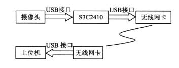
Figure l, the overall structure of the video surveillance system block diagram
2, the operating system customization
The core chip of the system hardware platform selects the S3C2410 processor and the maximum frequency can reach 203 MHz. The S3C2410 processor is an ARM920-based ARM920T processor core from Samsung and uses a 32-bit microcontroller with an O.18μm manufacturing process. The processor has a high degree of integration, which simplifies the hardware design of the application system and improves the reliability of the system. The development has also expanded 4MB of NOR Flash, 64 MB of NAND Flash and 64 MB of DRAM.
The system selected the Microsoft Willdows CE ("WinCE") operating system. WinCE is a compact, efficient and scalable 32-bit operating system for a wide range of embedded systems and products. It has a multi-threaded, multi-tasking and deterministic real-time, fully preemptive operating system environment that is dedicated to hardware systems with limited resources; at the same time, its modular design allows system developers and application developers to A variety of products to customize it, you can select, combine and configure WinCE modules and components to create a user version of the operating system.
In WinCE product development, there are two very important tasks, kernel customization and application development. Microsoft provides good development tools in both respects, namely, the kernel customization tool Platform Builder (abbreviated as "PB") and the application development tool Embedded Visual C++ ("EVC").
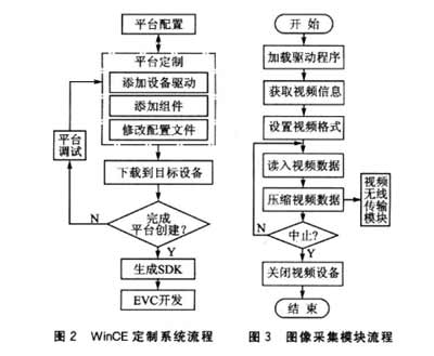
In the system customization process, the relationship between the various parts is shown in Figure 2.
3, video image acquisition
3.1 Camera Driver
The hardware resource of the image acquisition module selects the most widely used USB interface of the star micro camera on the market. This camera has a low cost and good imaging effect, and it has been used in this system to show a higher price/performance ratio. Before the system collects video, it is necessary to detect the set video source. After the system starts up, the WinCE operating system automatically detects whether the camera is connected. The system in the custom WinCE operating system, by modifying the operating system configuration and registry. You can make the system automatically load the driver ZC030x.dll for the camera under WinCE.
When the system automatically loads the driver, first copy the driver to the \WINDOWS folder, and then write the camera driver information to the registry:
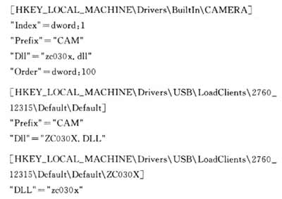
Among them, prefix is ​​the device file name, D11 is the file name of the driver, and Order is the index of the device file name. After the hardware configuration is completed, the operating system is started, and the driver can be automatically loaded and the application program is run for image acquisition.
3.2 Image Acquisition Program
The Vimicro micro camera adopts the Vimicro 301PLUS fast master chip. The chip is a high-performance image compression chip that outputs MIPEG video streaming data. MIPEG (Motion JPEG) is mainly based on the technology developed by static video compression. The feature is basically do not consider the changes between different frames in the video stream. It only compresses a certain frame, and usually achieves a compression ratio of 6:1. Its error stability is very good, it can obtain high-definition video images, but also can flexibly set the video clarity, compression frames.
The system directly obtains MJPEG video stream data from the camera driver. The image acquisition process is shown in Figure 3.
The main functions used by the image acquisition module are:
capInitCamera() is used to initialize the video device and get the number of currently available video devices;
capSetVideoFormat() Sets the video format and resolution. The video format used in this system is RGB24 with a resolution of 320×240 pixels;
capGrabFrsme() grabs an image from the driver and stores it in the buffer lpFrameBuffer;
capGetLastJpeg() converts the captured MJPEG format image to JPEG format and sends it to the wireless transmitter module.
capCloseCamera() closes the video device;
The video capture part also has related functions such as querying the video acquisition format, setting brightness, setting contrast, etc., and will not be described in detail.
4, video transmission part
4.1 Configuring a Wireless Network Card
The image transmission module is mainly realized through a wireless interface card of a USB interface. The wireless network adapter can be directly connected to the USB host interface integrated with the S3C2410 and operates in the 2.4 GHz ISM band. It uses direct sequence spread spectrum communication and complies with the 802.11g protocol. The transmission speed can reach 54Mbps and the indoor effective distance is 100 meters. LAN video transmission requirements. The system establishes a wireless local area network through the wireless network card between the development board and the host computer, and can realize seamless point-to-point connection. Through this wireless network, users can realize file transfer, video communication and other applications.
Development board-side wireless network cards also need to be loaded with drivers to operate. When customizing the WinCE operating system, the system first copies the driver of the wireless network card to the \WINDOWS folder, and then writes the drive information of the wireless network card to the registry. WinCE operating system will automatically detect whether the wireless network card is connected and load the driver program. At this time, the wireless network card can be called through the application program. In the wireless transmission, pay attention to put the development board and host in the same IP network segment.
4.2 Transmission of video data
The Real-time Transport Protocol (RTP) is a real-time streaming protocol that ensures that the media signal bandwidth matches the current network conditions, in one-to-one (umcast, unicast) or multicast (multicast). Real-time transmission of streaming media data in a network environment. RTP usually uses UDP for multimedia data transmission. The entire RTP protocol consists of two closely related parts: the RTP data protocol and the RTCP control protocol.
For the sending and receiving of system data, the RTP protocol stack provided by the open source code JRT-PLIB is used. JRTPLIB is an object-oriented RTP library that fully complies with the RFC1889 design. Developers can develop high-quality audio/video transmission programs as long as they have a basic understanding of the RTP protocol. It is ported to EVC, with minor modifications it can be applied to the ARM development board of the WinCE operating system.
4.2.1 Establishing RTP Data Transmission and Reception
The RTPSession class provided by JRTPLIB can implement RTP data sending and receiving. The initialization procedure for sending and receiving RTP data is basically the same. First set the timestamp, maximum RTP packet size, data timeout, and other session parameters, and then set the base port (note that this port must be even, the default value is 5000). After setting these parameters, you can use RTPSession's Create method to establish RTP data reception and transmission.
The data sender uses RTPIPv4Address(intIP, PORT_DATA) to establish a new address, and then use AddDestination to add this address to the sent address list. Then, send the RTP data by calling the SendPacket function.
After the RTP session is established at the data receiver and the target address is added, data can be received from the target address. At this point, the OnRtpPacket function will be called to receive the RTP data, and the load data will be retrieved and used in this function. In the OnRTPPacket function, the function zc030x_OutPicture(&m_pDlg->frame) is called to decode the received data. Finally, the function StretchDIBits() is called to display the video image in the current window.
4.2.2 RTP Control Protocol - RTCP
RTCP (Real-time Transport Control Protocol) and RTP together provide traffic control and congestion control services. During an RTP session, each participant periodically transmits RTCP packets. The RTCP packet contains statistics such as the number of sent packets and the number of lost packets. Therefore, the server can use this information to dynamically change the transmission rate and even change the payload type. RTP and RTCP are used together to achieve the best transmission efficiency with effective feedback and minimal overhead.
JRTPLIB is a highly encapsulated RTP library. After calling the PollData() or SendPacket() method, JRTPLIB can automatically process incoming RTCP datagrams and send RTCP datagrams when needed to ensure the correctness of the entire RTP session process. . In the RTP data transceiving, the control information that needs to be sent by the current RTP session may also be selected by calling the method provided by the RTPSession class, and the control information may be set.
Conclusion
The system is based on the S3C2410 platform and WinCE operating system, through the USB camera to capture real-time video information and compress it. Then, two wireless network cards are used to build a wireless local area network between the development board and the host computer, and real-time streaming transmission is used to achieve wireless transmission of video data. The entire system has the characteristics of stability, reliability, easy installation, and low cost, and can be applied in many fields such as remote monitoring, industrial control, video conferencing, visual telemetry, etc.
Pet Braided Sleeve,Braided Wire Sleeving,Pet Cable Sleeving,Pet Expandable Sleeving
Shenzhen Huiyunhai Tech.Co., Ltd. , https://www.cablesleevefactory.com