The production information platform of a natural gas company serves as a centralized system for monitoring and displaying key operational data. This platform provides three core functionalities: the qualification rate of equipment key parameters, the real-time status of equipment operations, and vibration equipment alarm monitoring. These functions are powered by the Zijinqiao real-time database, ensuring accurate and timely data processing.
The customer's functional requirements include:
1. **Device Key Parameter Qualification Rate**: The upper and lower limits for alarms are retrieved from a specified relational database table. Technicians can adjust these limits as needed. Zijin Bridge software calculates the key parameters based on these limits, computes the qualification rate, and stores the result in the designated relational database table.
2. **Equipment Operating Status**: Real-time values are continuously read by the information platform, while historical values are periodically stored in the relational database for future reference.
3. **Vibration Equipment Alarm Monitoring**: Real-time data is accessed directly through the information platform, but no historical data is required to be stored.
Real-time data for equipment operating status and vibration monitoring is obtained via the OPC Server interface, allowing for seamless integration with external systems. Meanwhile, the qualification rate of device key parameters and historical equipment operation data are sourced from the Zijinqiao real-time database and written to SQL Server for access by the production information platform.
The software version used in this system is Zijinqiao Real-time Database Software V6.5. A screenshot of the function window is provided below, although it was not designed for aesthetic purposes.
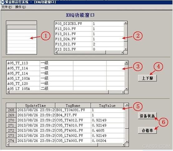
**Functional Description of Each Part**:
1. **Alarm Time Statistics Component**: This component tracks cumulative alarm time for each tag, which is essential for calculating the qualification rate.
2. **Real-Time Device Status Report**: Displays the current status of the equipment in real time and uses scripts to store corresponding bit values into the database.
3. **Alarm Upper and Lower Limit Report**: Retrieves the alarm thresholds for parameters from the relational database.
4. **Manual Reading Button for Qualified Rate Alarm Limits**: Allows users to manually fetch alarm limits from the relational database.
5. **Data Check Report for the Current Day**: Enables users to review data that has been successfully written to the database.
6. **Device Status/Pass Rate View Button**: Provides access to the most recent day’s device status or pass rate data.
While parts 5 and 6 are not essential for the main functionality, they serve as tools for developers to verify whether data has been correctly stored in the remote database.
This article primarily focuses on the "device key parameter qualification rate" feature. The "equipment operation status" section is similar, and the "vibration monitoring" part does not require storing data in the relational database, so it will not be elaborated further.
Next, we'll explain the key parameters pass rate function in detail.
**Key Parameters Pass Rate Function Section**:
1. A new alarm time statistic component named "Alarm1" is added to the window. Specific tags are included in this component, and the bit number is configured to use its own alarm limit value.
2. A new "report relation data source point" is introduced in the point configuration to connect to the relational database for data retrieval.
3. A new free report is created, linked to the relational database and the new report relation data source point, and named "Fr1".
4. A table template is created to define the structure of the data table. The SQL function cannot generate a table automatically, so a predefined template is necessary. The template includes fields such as "date", "bit number name", "value", and "weight".
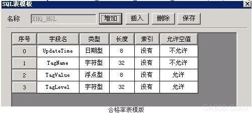
The table template defines the structure of the qualified rate data table, with specific field names like "UpdateTime", "TagName", "TagValue", and "TagLevel". After the table is created, the template is no longer needed, and the first table is created using a button, after which the button is removed.
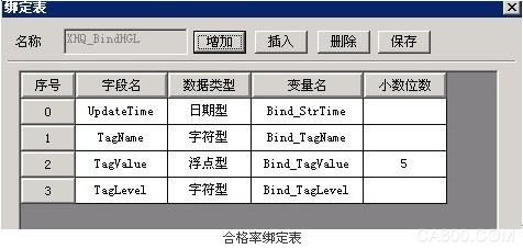
5. A binding table is established to facilitate data insertion into the relational database. The field names in the binding table must match exactly with those in the table template. Four intermediate variables are also defined to correspond to the four fields of the data table.
6. **Scripting**: Due to limitations in the Zijinqiao Real-time Database Software V6.5, the window cycle execution script cannot exceed 15 minutes. To achieve the desired functionality, several integer window variables are defined, including `w_cID`, `w_t1`, `w_t2`, `w_t3`, `w_t4`, and `w_TBegin`.
**Window Entry Script**:
Upon entering the window, the following script is executed. It sets the time variables for the next day's zero point, initializes the start time for the alarm statistics component, and connects to the database.
**Cycle Execution Script**:
Every day, five minutes before midnight, the alarm limits for critical parameters are read from the relational database into the report "Fr1". This ensures that any changes made by technicians are reflected in the calculation of the pass rate.
After reading the alarm limits, the script proceeds to calculate the pass rate based on the alarm limit values. Once the alarm statistics component completes its task, the statistical data is extracted, calculated, and stored in the database table.
**Exit Window Script**:
When exiting the window, the script disconnects from the relational database.
The key to the entire script lies in the periodic execution logic. By using time variables and conditional checks, the script ensures that the required actions are executed around the daily zero point without exceeding the 15-minute cycle limit.
In summary, this example demonstrates how to use a report relationship data source point in combination with a free report to retrieve data from a relational database. While this method simplifies operations and reduces the need for extensive scripting, it does not support writing data back to the database. On the other hand, using the built-in SQL functions of the Zijinqiao real-time database allows for full control over database operations, though it requires more setup, such as creating table templates, binding tables, and writing custom scripts.
Countdown Timer
FUNCTION DESCRIPTION
Countdown
socket has an AC outlet, the maximum can output 230 V16A of power,
there are two control modes, that is, countdown off and countdown on. It
is convenient to control the equipment which needs to switch off or
turn on AC. improve the safety of the use of some equipment and save
more energy.
SET Timer
1,Countdown
plug in the socket, all indicator lights red flash three times, at this
time the socket has no output, for the normal state, into the countdown
state. Click the button, the first red light up, the socket output
after an hour off, and then short press the button can set the socket
timing of 2 H.4H.6H.8H.10H.OFF.
2,Long
press button 3s, all indicator lights green flash three times, at this
time the socket has output, for the regular open state, into the
countdown on state. Click on the button, the first green light on, the
socket is closed an hour later, and then press the button to set the
socket countdown 2 H.4H.6H.8H.10H.OFF.
3,Press button 3 longer S, all indicator lights red light flash 3 times again into countdown mode.
4,Select
the required countdown time mode, the corresponding mode countdown
lights up, start countdown until the end of the countdown time. The
outlet that controls the output will start or stop the output.
5,After the countdown starts, the time indicator will change automatically from high to low until the countdown is over.
NOTE:
1,Check that the power connection is good.
2,Use only indoors and in dry places.
3,This product does not convert AC voltage.
4,Maximum load not exceeding 16A 3680W.
5,Grounding is required for safety.
6,Any questions, please contact the electrician.countdown timer socket, countdown timer plug, Countdown digital timer, Countdown socket, countdown switch socket
NINGBO COWELL ELECTRONICS & TECHNOLOGY CO., LTD , https://www.cowellsocket.com