Wu Changrui, Kong Chao, Yan Yinghui, Yan Fan, Cai Huizhi, Institute of Acoustics, Chinese Academy of Sciences
Key tips: Broadband technology; Phased array radar; High performance signal processing; Serial RapidIO protocol; VPX bus standard
1 Overview
A variety of application backgrounds require that modern radars are not limited to the detection of targets, ie radar position parameters (distance, speed, angle, etc.), but also the attributes of the target and the subtle characteristics of the target, such as target size, shape, and More accurate target position parameters. Broadband phased array radar is one of the radars that satisfies the above performance. Broadband phased array radar uses broadband technology and phased array radar technology to combine the advantages of phased array radar technology: (1) fast beam scanning and beamforming capabilities; (2) detection and tracking of dense targets; 3) Long-range target detection capability. At the same time, it also has the advantages of wideband radar technology: (1) high resolution target imaging capability; (2) high-precision target characteristic measurement capability; (3) non-cooperative target classification recognition capability; (4) Low RCS detection capability .
Broadband phased array radar signal processing has the application background of massive computing requirements. At the same time, broadband phased array radar is often used in airborne and shipborne environments, and imposes more stringent requirements on the system's anti-vibration and impact resistance. . Traditional radar signal processing system adopts 32-bit wide or 64-bit wide parallel bus transmission technology, DSP chip processing technology and pin connector technology. It can not meet broadband phased array radar signal in terms of communication capability, processing capability and system seismic performance. The need to deal with. Therefore, how to design a new system signal processing system with higher bandwidth, faster processing speed, and adaptability to harsh environment to meet the application requirements of broadband phased array radar has become a hot topic at home and abroad.
This paper presents a high-performance signal processing system based on the VPX bus standard. The system uses a combination of high-speed serial communication protocols to achieve flexible transmission. FPGA technology and PowerPC technology combine to achieve high-performance data processing.
2 High-performance radar signal processing system
In order to improve system robustness, stability and compatibility, the new radar signal processing system designed in this paper adopts an open VPX architecture, a combination of high-speed serial technologies, and a combination of FPGA technology and PowerPC technology. The cell structure uses the high-speed differential connector MutliGig RT2 technology to achieve ultra-high power and large bandwidth transmission in harsh environments.
2.1 Status of System Architecture Development
The architectural standards refer to a series of specifications including the mechanical dimensions, power requirements, thermal design, electrical standards, management signaling, communication methods, and interconnect architecture of the equipment. Current radar signal processors mainly use the CPCI (CompactPCI) architecture and the VME (Versa Module Eurocard) architecture, which are derived from the specifications of the PICMIG organization and the VITA organization.
However, in the era of massive data, the bus bandwidths of the above two architectures cannot meet the requirements of practical applications. Therefore, the PICMIG and VITA organizations respectively introduced the CPCI Express bus standard and the VPX bus standard, achieving an architectural upgrade and a breakthrough in bandwidth. The CPCI Express architecture supports general-purpose operating systems and hot-pluggable technology. It has extensive software adaptability and flexibility. The VPX has a more robust mechanical structure and stronger cooling capability, supporting and independent of multi-processor computer systems. It has a good prospect in some demanding areas of high-speed transmission. At the same time, the two have many common features, such as the open architecture system, high reliability, easy maintenance and expansibility. Therefore, it is difficult to distinguish between wins and defeats.
2.2 VPX Architecture
Due to the more emphasis on the harsh environment and system cooling considerations, this article uses the VPX architecture. VPX bus is the natural evolution of VME technology, and its use of high-speed serial bus instead of parallel bus is its main change. Table 1 lists the specifications and performance comparisons of different VITAs.
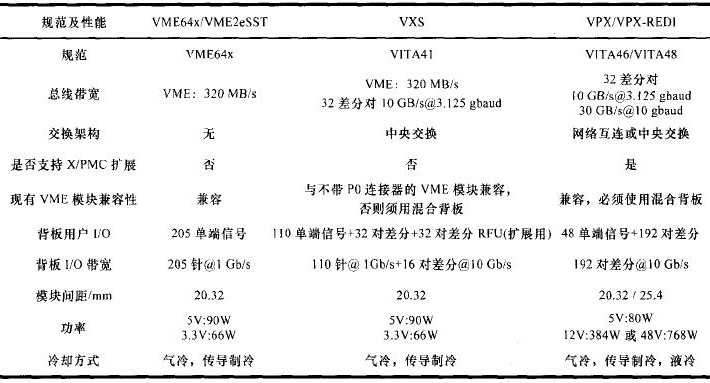
Compared to other bus standards of VITA organization, VPX bus has the following characteristics:
(1) High density and flexibility in structure. The VPX bus complies with IEEE 1101 3U and 6U standards, while allowing different structures to ensure compatibility with legacy systems.
(2) Enhanced bandwidth. The use of high-speed serial Connectors drastically increases the bus bandwidth.
(3) Enhanced power supply design. The VPX specification meets the power requirements of multiprocessor technology by increasing the backplane power supply and a more well-designed heat dissipation system (conduction, liquid cooling).
(4) Compatible with various high-speed serial protocols.
(5) The new MutliGig RT2 high-speed differential connector with silicon wafer structure has the advantages of tight connection, low insertion loss and low bit error rate. Each differential pair supports up to 10 Gb/s data bandwidth, and the silicon wafer Both have ESD ground and contact layers to prevent accidental discharge during operation.
2.3 Transmission Technology Combining Various High-speed Serial Communication Protocols
The 32-bit wide or 64-bit wide parallel bus in conventional radar signal processing systems uses system synchronization technology. The bus frequency using this synchronization technique is limited by its bit width. The crosstalk between the buses becomes more and more serious with the increase of the frequency, the signal synchronization is more and more difficult, reach the certain frequency, the bus data begins to be distorted, can't raise the transmission frequency. Therefore, parallel buses using system synchronization cannot meet increasing bandwidth requirements.
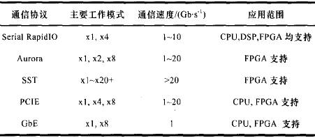
High-speed serial bus transmission technology based on the Low-Voltage Differential-Level Standard (LVDS) can make up for these deficiencies and the transmission rate can reach Gb per second. Such as Serial RapidIO protocol, Aurora protocol. The above protocol adopts the serial transmission technology of clock packing and clock recovery technology. It is no longer necessary to consider issues such as Skew and jitter between the data line and the clock line, and it is easier to increase the transmission rate, reduce the number of pairs, and reduce the implementation cost. With signal pre-emphasis and equalization, better signal integrity can be achieved. Serial RapidIO technology and Aurora technology are implemented by the Multi-Gigabit Transceiver hard core in the FPGA. Due to the limited number of hard-core Multi-Gigabit Transceivers in the FPGA, the above two protocols are preferentially used for inter-board communication. The communication between FPGAs and FPGAs within a board can use the SST (source-synchronous LVDS interface) protocol. The SST protocol utilizes the features of FPGA to excel in parallel transmission of large amounts of data and serial-to-parallel conversion technology to achieve broadband data transmission. It is a high-speed serial transmission technology that does not require Multi-Gigabit Transceiver hard core resources.
To meet the system's flexibility, compatibility, and different transmission bandwidth requirements, the new radar signal processing system uses a combination of high-speed serial communication protocols. Table 2 analyzes and compares the main working modes, communication speeds, and application ranges of the current high-speed serial communication protocols.
2.4 Combination of FPGA Technology and PowerPC Technology
In the field of radar signal processing, the main processing units at present are DSP, FPGA and CPU. The DSP+CPU architecture, FPGA+CPU architecture, or a hybrid structure of the two is the main processing unit architecture used in current systems. However, with the development of semiconductor technology, FPGAs have replaced the traditional DSP trend by virtue of their natural programmability, large data volume parallel processing, embedded DSP hard core and high-speed serial Transceiver transmission technology. At the same time, FPGAs support multiple communication protocols and level standards and can act as a bridge between multiple protocols in future radar signal processing systems. Freescale’s MPC8641 D is a high-performance CPU that uses the PowerPC architecture for radar signal processing systems. It not only has a mature operating system, but also good at task scheduling and floating-point operations. The structure of the processing unit combined with the MPC8641D and FPGA is used in this paper to enable the system to obtain more flexible processing capabilities.
3 Engineering Applications
Prior to the advent of the VPX, the radar system faced two most fundamental performance limitations: the maximum data bandwidth supported by the bus signal pins and the maximum power provided by each board slot. VPX effectively solves the above two problems through high-speed connectors and supporting advanced interconnect architectures.
DBF is a typical data operation module in a wideband phased array radar signal processing system. DBF is a full array element of the spatial filter, the distribution of the processing structure requires interactive transmission, with a large amount of data and a large number of ways and so on, relying on the traditional parallel bus can not be completed.
The DBF processing system based on VPX bus designed in this paper solves this problem through various high-speed interconnection interfaces. The system consists of a fiber-optic Ethernet access board, three FPGA pre-processing boards, an MPC8641D processing board, and a 5-slot VPX backplane. All boards in the system are designed with 6U VPX mechanical dimensions. Figure 1 shows the system block diagram. Figure 2 shows the backplane interconnection of the system.

Fig.1 Block diagram of DBF processing system for broadband phased array radar with VPX bus
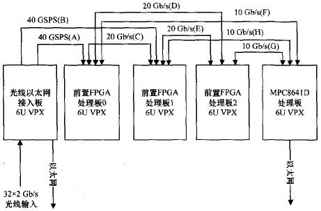
Figure 2 Backplane Interconnection of DBF Processing System with Phased Array Radar in VPX Bus
The system RF front end transmits data of 32 sub-array signals from 32 optical fibers. Among them, each fiber carries 8 array element sampling results, totaling 2 Gb/s. The solution of this DBF processing system is as follows:
(1) Optical Ethernet The access board receives 32 optical fiber data through eight QSFP (Quad Small Form Factor Pluggable) modules to perform photoelectric conversion to form 32 64 GBPS electrical signals. Through the backplane (Figure 2, A, B 2) to the FPGA pre-processing board 0 and board 1.
(2) Each FPGA pre-processing board receives 16-channel 32 Gb/s signals for half-beam formation, and the two boards exchange data through C in FIG. 2 .
(3) Two-way half-beam forming results The final beamforming calculation is performed by transmitting FPGA pre-processing board 2 in FIG.
(4) The beamforming weight coefficients are calculated by the MPC8641D and transmitted to the FPGA pre-processing board through the F, G, and H channels in Figure 2.
From Figure 2, it can be seen that the large amount of data exchange handled by the DBF is achieved through the VPX backplane in the chassis. Each channel of the backplane can meet the bandwidth requirement of 32 channels of 64 Gb/s beamforming. Among them, channels A and B run two GSPS Aurora protocols; channels C, D, and E all run one GSPS Aurora protocol; channels F, G, and H run the GSPS RapidIO protocol. The DBF data multiply and accumulate calculation is completed by the FPGA XC5VSX95T on the FPGA pre-processing board. The FPGA has a rich DSP48E core.
This VPX chassis provides 5V/10A, 3.3V/10A, and 12V/50A power supplies. The total output power of the chassis power module is 683 W. The system uses a combination of air cooling and conduction cooling.
4 System Performance Test
4.1 Computational Capability Test
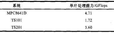
Computing power is the most critical performance indicator of a signal processing system. The system performance test is first of all a computational capability test. This paper uses 1024-point single-precision floating-point complex radix-2 FFT algorithm to test the computing power of different processors. Table 3 shows the comparison of the processing unit's computing power. It can be seen that the computing capability of the MPC8641D is 2.7 times that of the DSP TS101 and 1.3 times that of the DSP TS201.
4.2 Communication Capability Test
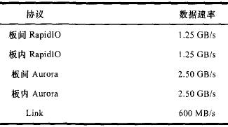
The communication capability is another key performance indicator of the signal processing system, which directly affects the overall performance of the signal processing system. In this paper, two FPGAs in the board or board are used to instantiate test protocol IP cores respectively, and the link data rate is tested under the condition that the link BER is lower than 10-12. Table 4 shows the comparison of the test results of the RapidlO, Auror, and DSPTS201 Link communication capabilities. It can be seen that compared to the DSP TS201 Link data rate, the communication capability of the system in this paper is increased by 4 to 8 times.
5 Concluding remarks
This paper presents a high performance broadband phased array radar signal processing system. The system adopts a switching-based VPX bus standard, a combination of high-speed serial communication protocols, and a processing unit architecture that combines FPGAs and high-performance CPUs. It has the processing power required for broadband phased-array radars and supports each. Kind of bandwidth. The test results show that the system supports large bandwidth and super power, and has the ability to handle high-bandwidth data in harsh environments. It is the development direction of the next-generation radar signal processing system.
We make OBD connector with terminal by ourselves, soldering type and crimping type are both available. Also 12V and 24V type. OBD1, OB2, J1939, J1708, J1962, etc. Also molded by different type, straight type or right-angle type. The OBD connector cables used for Audi, Honda, Toyota, BWM, etc. We have wide range of materials source , also we can support customers to make a customized one to replace the original ones.
OBD Connectors,Sae J1708 Connector,Sae J1939 Connector,OBD2 Diagnostic Connectors,Diagnostic Connector,Deutsch Diagnostic Connector
ETOP WIREHARNESS LIMITED , http://www.oemmoldedcables.com