Most products that use DC-DC converters or motor inverters must rectify the mains AC voltage, for example, most industrial equipment (motor speed controllers, chargers, telecom system power supplies, etc.) and common consumer electronics. Products (white goods, TV, computers, etc.).
Traditional diode rectifier bridges are the most commonly used AC voltage rectification solution. A power factor controller is often added behind the rectifier bridge to ensure that the mains current waveform is approximately sinusoidal. However, diode rectifier bridges cannot control the inrush current. Two thyristor rectifiers (SCRs) are used to replace the two diodes, and the new control rectifier bridge limits the inrush current when connected to mains.
This article presents several front-end topologies and some design techniques related to hybrid rectifier bridges and effective overvoltage prevention. The experimental results show that the 4 kV to 6 kV surge voltage withstand design is easy to implement and the cost is not high.
Inrush current limiting scheme (ICL) and standby power issues
The disadvantage of diode rectifier bridges is that they cannot control the inrush current because the DC output capacitors are suddenly charged when plugged into a mains outlet.
Strong inrush currents can cause problems for the system, such as insurance failure, damage to components such as diodes, and excessive current stress on the grid. If the inrush current is not limited, the starting current rises quickly, and it is easy to reach 10-20 times the steady-state current. Therefore, the parameters of the line components must be increased to enable a large current to be transmitted in a short time. In addition, a sudden increase in line current will result in a voltage dip, which will reduce the input power of other loads. Lamps or displays connected to the same line will be flickering or flickering. To avoid these harmful phenomena, the IEC 61000-3-3 electromagnetic standard specifies the maximum allowable voltage fluctuation and the maximum allowable inrush current.
In order to meet this standard requirement, the current limiting method is to limit the capacitor inrush current by using a fixed-resistance resistor or a thermistor (RLIM in Figure 1a). The thermistor usually has a negative temperature coefficient characteristic (NTC). Therefore, the thermistor has a large impedance at a low temperature, that is, a small impedance at a steady state. In order to control the power consumed by the resistor itself at steady state, a low resistance resistor is required. A better solution is to connect a resistor in parallel with a switch to form a bypass that turns the switch on at steady state and the current bypasses the resistor.
This bypass switch usually uses a mechanical relay (S2 in Figure 1a). The disadvantage of this solution is that the RLIM resistor is always connected to the mains line, and the diode rectifier bridge is powered as usual even if the application enters standby mode. Since the DC capacitor (C) is still in a charged state, there is a standby power loss. To reduce power loss, it is necessary to connect a switch (S1 in Figure 1a) to the mains line. This switch opens when the device enters standby mode, which disconnects the diode bridge from the line.
The hybrid rectifier bridge is a smarter inrush current limiting solution, as shown in Figure 1b. With the progressive soft start of the thyristor rectifier (SCR), the output capacitor is slowly charged to limit the inrush current. The thyristor rectifier is activated at the end of each half cycle of the line voltage, at which time the voltage applied to the capacitor is reduced. By gradually reducing the conduction delay of the thyristor rectifier, the conduction time of the thyristor rectifier is prolonged, thereby increasing the applied electrical energy on the DC capacitor.
If an inductor is connected in series with the line (L in Figure 1b), this solution will work. In practical applications, this inductor is free, because most DC bridge-based applications have switched-mode power supplies or motor inverters, and in either case, a high-frequency switching filter is required. Most EMI filters have a common-mode inductor that produces a stray differential inductor.
This solution also requires an auxiliary power supply to power the microcontroller before the DC output capacitor is charged, ensuring soft-start operation of the thyristor rectifier.
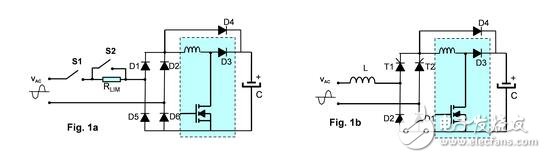
Figure 1: Surge current limiting circuit based on resistors and relays (a) and surge current limiting circuit based on hybrid rectifier bridge (b)
Therefore, this overall solution to limit inrush current and control standby loss is to replace one current limiting resistor and two relays with two thyristor rectifiers. Compared with mechanical relay technology, semiconductor solid state relays are inexpensive and overcome the following shortcomings of mechanical relays:
· The control current consumption caused by the coil is large
· Open switch caused by mechanical vibration
· Acoustic noise generated by mechanical contacts
· Fire in a flammable environment (switching arc)
· Low reliability (relay switch operation at high DC voltage or current)
Front-end protection transition to surge voltage
Like a diode rectifier bridge, the hybrid rectifier bridge is also directly connected to the mains socket. If there is a surge voltage, it is likely to burn the rectifier bridge and the PFC chip (for example, the bypass diode D4 in Figure 1).
In the anti-surge impact test procedure described in the IEC61000-4-5 standard, positive and negative surge voltages of different phase angles must be applied.
Apply positive surge voltage at the peak voltage of the mains
We apply a 4KV positive surge voltage at a 90° phase angle, as shown in the schematic of Figure 2 (no PFC). To simulate the worst application environment, we choose a 2 for L? H inductance, C is a 100? F capacitor. The thyristor rectifiers are two 50A TN5050H-12WY, while the D1, D2 and D4 diodes (PFC bypass diodes) are STBR6012-Y rectifiers.
At a 90° phase angle, T1 and D1 conduct. The surge increases the current and causes D4 to conduct because the PFC inductor maintains voltage. Inrush current bypass diode D4 to avoid burning PFC freewheeling diode (D3).

Figure 2: Overcurrent stress during positive surge voltage (schematic diagram, D4 is a PFC bypass diode)
As shown in Figure 2, during a surge, the peak current of T1 reaches 1730 A (the same is true for D1 and D4 currents). The current pulse width is equivalent to 30 ? s long half sine wave. This current stress value is much lower than the tolerance of STBR6012-Y and TN5050H-12WY.
If the applied inrush current is higher than the current withstand capability of the thyristor or diode, there are two ways to reduce the overcurrent (both methods can be used together):
· The method of increasing the differential inductance helps to reduce the peak current, but it also increases the overcurrent pulse width slightly.
· Adding a varistor to the line input helps to reduce the peak pressure shock on the circuit and also reduces overcurrent.
As shown in Figure 2, the inrush current boosts the VDC output voltage to 650 V. This voltage is applied in reverse to T2 (because diode D1 is also turned on when T1 is turned on) and D2. Therefore, a device of at least 800 V must be used. The TN5050H-12WY and STBR6012-Y are 1200 V with high voltage margin.
If the reverse voltage exceeds the tolerance of the thyristor or diode, a larger value of the output capacitor or a low internal parasitic capacitor can be used to control the surge voltage more effectively.
Applying a negative surge voltage at the peak voltage of the mains
If the applied negative surge voltage is a 90° phase angle, the hybrid rectifier bridge works a bit more complicated.
Figure 3 shows the circuit continuity sequence for this case.
· Phase A: The hybrid rectifier bridge works normally before the surge is applied. VAC is a positive voltage, T1 and D1 are on, and line current (IL, green dashed line) flows from L to N, passing through T1, D1 and the output capacitor.
• Phase B: A negative surge voltage is applied, so the VAC polarity becomes negative, which means that the negative current (red dashed line) will flow from N to L.
· Stage C: After the VAC voltage becomes negative, the line current drops. When the IL current crosses zero, D1 turns off. This means that the entire line voltage is now applied to T2 (VT2 red arrow).
The C stage must be handled with care. In fact, if the voltage is higher than the breakdown voltage of the thyristor, the device may be burned.
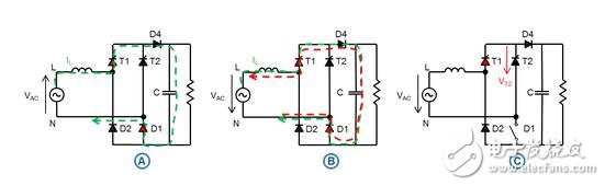
Figure 3: 90° negative surge voltage test hybrid rectifier bridge working sequence
Transil-based protection mechanism
An overvoltage protection device Transil (Fig. 4) is connected between the anode and the gate of the thyristor to prevent T2 from being burnt in the C stage. In phase C, the voltage will rise to Transil's breakdown voltage (VBR), triggering the Transil diode to conduct and apply current to the thyristor gate. Then, the thyristor rectifier is turned on. Figure 4 depicts this operation:
· Phase A: At the end of point 1, the VAC voltage becomes negative.
· Phase B: At the end of point 2, the line current voltage crosses zero.
· Phase C: T2 is turned on at point 3, the voltage is higher than the Transil breakdown voltage, and the maximum voltage applied to T2 is limited to 430 V. Then D2 is also turned on, applying a surge to charge the output capacitor.
· Stage D begins after point 4. Inrush current is applied to the output capacitor through T2, D2, and D4. T1 and D1 are turned off
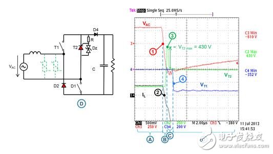
Figure 4: 90°1 kV negative surge voltage test of hybrid rectifier bridge based on TN5050H-12WY thyristor rectifier
We chose a 1,5KE400CA Transil diode for the test. This diode is especially important to limit the peak voltage of the clamp to a very low level (430 V). In phase C, the absolute value of the negative voltage on D1 is the sum of VT2 and VDC. If the output DC voltage is 325V, the maximum negative voltage on D1 is 755 V (within the allowable range of STBR6012-Y). A higher voltage Transil or a low power Transil (1,5KE400CA is a 1500 W Transil) will cause a higher clamping voltage, resulting in a higher voltage applied to D1.
A resistor connected between the gate and cathode of T2 is used to shunt the current output from the Dz transil diode to avoid spurious triggering caused by dV/dt.
Rheostat-based protection mechanism
If you don't want the thyristor to turn on when the voltage is higher than 430V, or when the thyristor is triggered by Transil, if the inrush current is higher than the SCR ITSM value, we still have a solution, that is, in the rectifier bridge At the input, change the Transil diode to a voltage suppressor, for example, a metal oxide varistor (green dashed line in Figure 4). After the varistor is placed in the EMI filter, the filter impedance (especially the differential inductor of the common choke) limits the current absorbed by the varistor.
Multiple varistors are connected in parallel to better limit the surge voltage, avoiding T2 conduction when a 90° phase angle negative surge voltage is applied (T1 is conducting when a 270° phase angle positive surge voltage is applied).
Surge voltage withstand capability depends on whether the varistor can limit the surge voltage below the VRRM of the VDSM/VRSM and D1/D2 diodes of the T1/T2 thyristor rectifier. The overcurrent of the thyristor rectifier is no longer a problem. For example, four 385 V 14 mm metal oxide varistors (MOVs) are connected in parallel to a typical EMI filter. When the surge voltage reaches 6 kV, the voltage of the hybrid rectifier bridge is limited to 1100V, which is much lower than TN5050H- Breakdown voltage of 12WY VDSM and breakdown voltage of STBR6012-Y rectifier. Therefore, this circuit is typically able to withstand 6 kV surge surges.
in conclusion
Why choose this topology?
Reduce power loss, size, and reliability (relative to relays and passive current limiters).
Robust solution with next-generation thyristor rectifiers and front-end topology.
n20 motor,n20 gear motor,n20 micro gear motor
Shenzhen Maintex Intelligent Control Co., Ltd. , https://www.maintexmotor.com