1. Introduction With the wide application of lithium-ion batteries, their safety issues have received more and more attention. Real-time detection of the parameters of the lithium-ion battery can effectively avoid the unsafe use of the battery, and can maximize the performance of the battery. Some application areas are difficult to lay the line due to conditions, and need to monitor the battery remotely, such as street lamp battery management; or because of the large number of uses, it is more troublesome to connect the monitoring lines one by one, such as battery status monitoring in the base station power management or a large number of communication stations. In a centralized occasion, the collected data can be transmitted and managed through a wireless network.
The system is mainly composed of lithium ion battery state data acquisition, signal wireless transmission, data processing and other parts. The system block diagram is shown in Figure 1. The front end is composed of a state parameter acquisition module and a wireless emission control module. The data acquisition part includes measuring the voltage, current, internal resistance and temperature of the lithium ion battery pack, and the sampling data is initially processed by the single chip microcomputer, and then the transmitting chip is controlled. Modulation transmission. The back end of the system consists of a wireless receiving control module, a single-chip microcomputer and a serial port circuit, and a local computer. The receiving chip demodulates the signal, and the MCU receives the data and processes it. The valid data is transmitted to the local computer through the serial port, and the monitoring personnel can pass the status. The data is analyzed to grasp the working state of the battery pack, and the abnormal battery is processed in time to ensure the reliability of its work.
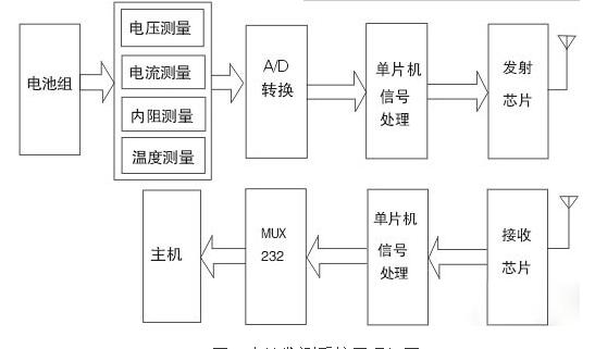
Figure 1 Block diagram of the battery monitoring system
According to the various application environments and system management purposes of the lithium-ion battery pack, the state sampling device adopts a modular design, which mainly includes: a lithium ion battery voltage measuring circuit, a current measuring circuit, an internal resistance measuring circuit, and a temperature measuring circuit. Parts [1, 2]. The detection module performs A/D conversion on the collected signals and transmits the data to the control module. The high-precision, high-efficiency data acquisition module used in the design takes into account the principles of specialization and generalization, and the configuration is flexible. The system can control the gating of each module by the single chip microcomputer. Each module can be used alone or in combination, which can adapt to different application occasions.
2. Experimental System Compared with wired data transmission, wireless data transmission is characterized by the use of radio frequency signals to transmit and receive data packets. The wireless data transmission mainly consists of a wireless data terminal, a main receiver and a main monitor, and a serial port communication is used between the main monitor and the main receiver. The entire transmission system is designed to achieve the purpose of online monitoring of lithium-ion battery state, so the accuracy, real-time and power consumption of data transmission is the key to the design.
2.1 Transmitter 2.1.1 Design of Transmitter Circuit The hardware circuit of the transmitter of the wireless transmission system is mainly composed of data acquisition module, single chip microcomputer and RF transmitter chip. The circuit is shown in Figure 2.
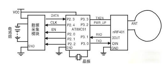
Figure 2 Transmitter circuit
In this paper, ATMEL's AT89C51 single-chip microcomputer is used to control the transmitting system. The single-chip control data acquisition module samples the voltage, current, internal resistance and temperature of the battery. The wireless transmitter chip adopts the integrated wireless transceiver chip nRF401 from Nordisk, Norway. The nRF401 chip integrates high-frequency transmit/receive, PLL synthesis, FSK modulation/demodulation and multi-channel switching, etc., in low-cost digital wireless communication. The application has outstanding technical advantages [68].
2.1.2 Transmitter software design According to the design of the working mode of the lithium ion battery monitoring system, the basic process of software design is shown in Figure 3.
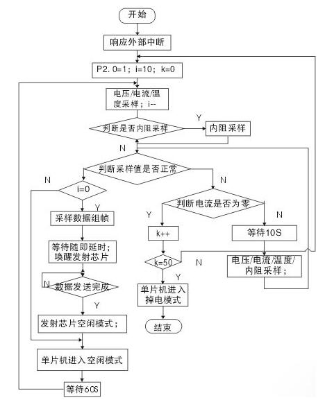
Figure 3 transmitter flow chart
The sampling of the parameters of the lithium-ion battery pack is divided into several states: one is timing sampling; the other is trigger sampling, there are two types of triggers, and the other is that the monitoring circuit in the stationary state enters the working state when detecting the operating current of the battery pack. , start timing sampling; the other is the trigger sampling of internal resistance. The monitoring module is in the power-down mode when the system is not working, and the microcontroller uses the operating current in the system as an external interrupt trigger. Once the system has operating current, the microcontroller responds to the interrupt and enters the operating mode. Firstly, the working mode of the sampling module is set, and the battery state parameter is sampled. After waiting for a certain sampling delay, the single chip reads the sampling data for analysis, determines whether the data is sent, and determines whether the sampling data is sent according to the specific application system. Pre-set in the microcontroller. The following settings were made for the monitoring system:
(1) The monitoring system is applied to the on-line monitoring of a 4-string 5Ah lithium-ion battery pack. The system operating current is 1A and the maximum current value is 5A. The application field of the battery pack has a protection circuit, the overcharge protection voltage value is 4.2V, the overdischarge protection voltage value is 3.3V, and the overcurrent protection current value is 3A;
(2) The normal range of the battery pack operating state parameters set in the monitoring system is: working voltage is 3.4V ~ 4.1V, working current "2.5A, working temperature is -10 °C ~ 60 °C, internal resistance value is the initial value Less than 2 times;
(3) When the battery is in the normal working range, the monitoring system samples the voltage, current and temperature every 60s. After sampling 10 times, the arithmetic average of the 10 samples is taken and then sent. Under normal circumstances, the battery pack starts the internal resistance sampling circuit for sampling 10 times per cycle;
(4) If the battery status parameter exceeds the normal working range, the sampling circuit enters the fast sampling stage, samples the voltage, current and temperature once every 10s, takes the arithmetic mean of the 10 samples, and starts the internal resistance sampling circuit of the battery pack. The inner group samples and sends the sampled data.
2.2 Receiver 2.2.1 Design and implementation of the receiver circuit The hardware circuit of the receiver is composed of the wireless transceiver chip nRF401, the single-chip AT89C51, the serial port chip MAX232, and the main control computer. The circuit is shown in Figure 4.
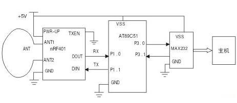
Figure 4 Receiver circuit
ANT1 and ANT2 are the inputs of the LNA at the time of reception, and the TXEN pin of the receiving chip nRF401 is grounded and operates in the receiving mode. When the nRF401 receives the valid signal, the input signal is amplified by the low noise amplifier, and is converted by the mixer. The converted signal is amplified and filtered before being sent to the demodulator, demodulated by the demodulator, and demodulated. The digital signal is output to the microcontroller at the DOUT terminal. The single chip determines whether the signal is a valid data frame, first extracts the received check code to calculate the checksum, determines whether the checksum is correct, and if so, extracts the ID code, voltage, current, internal resistance, and temperature value respectively through the serial port. The circuit is sent to the terminal control computer, otherwise the MCU ignores the data and waits for the next reception.
2.2.2 Receiver software According to the above hardware circuit design, the basic idea of ​​system software programming is as follows [3]: The transmitter MCU first sets the working mode of the sampling chip: there are three samples for the voltage, current and temperature of the battery respectively. State. The MCU receives the status information sent from the detection part and determines whether to send it. For determining the transmitted monitoring data, since the system can send data of multiple monitoring stations to the same host, it is necessary to add an ID number to each monitoring object, and since there may be a small number of errors in the sending process, Therefore, it is necessary to generate a checksum at the transmitting end, and combine the data into a data frame according to a fixed frame format and then send it to the transmitting chip. The data frame format is preamble + sync character + ID code + voltage + current + temperature + check code. Since the packet length is fixed, the counting method can be directly used to judge whether the transmission is completed.
After receiving the signal in the leading field format, the receiving end MCU generates a serial interrupt, the interrupt program is responsible for receiving the data frame, and finally performs a CRC checksum calculation on the received data frame, compares it with the received checksum, and verifies Checksum, if the checksum is correct, pass the data to the computer through the serial port. If the checksum is wrong, wait for the next reception.
3. Analysis of experimental results In the experiment, the system wirelessly monitors 4 polymer lithium-ion battery packs with a rated capacity of 5 Ah. During the operation of the battery pack, the voltage and internal resistance are monitored separately. The measured values ​​of the front end of the system and the monitoring results of the terminal are shown in Table 1:
Table 1 Battery pack status parameter monitoring results (voltage / internal resistance)
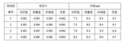
Tab.1 Monitor result of batteries state parameter (voltage and resistance)
In this design, the monitoring error range of the working state parameters of the lithium ion battery pack is: the voltage monitoring error is within 0.005V; the internal resistance error is within 1mΩ. The reason for the analysis of the system error is mainly due to the error caused by the front-end detection circuit and the error caused by the signal A/D conversion. The wireless transmission system can realize the stable transmission and reception of the signal within 20 meters of the transmission distance, and the error rate is lower than 0.1%. .
4. Conclusions This paper studies the wireless transmission of battery monitoring system, designs a remote wireless data transmission system, and realizes the collection and storage of battery parameter signals with simple hardware circuit. The software design reduces the system's power. Consumption and transmission errors. Experiments show that the wireless monitoring system can realize on-line monitoring of multiple independent power sources, stably transmit and receive its status parameter signals, and provide timely and effective battery pack status information to the monitoring terminals.
references:
[1] Ke Zhaosheng, Liu Baoqi, Guo Shuxu, etc. A wireless temperature measurement system [J]. Metrology Technology, 2004, No. 4: 6-8.
[2] Zhang Xiongxi, He Jiabin. Design and implementation of remote wireless monitoring system [J]. Electronic Design Applications, 2003, 8: 36-37.
[3] Xu Aijun. MCU high-level language C51 application design [M].
Headphone speaker:
Headphone speaker is a king of speaker unit which is used for headphone, it also called headphone driver. These speakers have high sound pressure level, fast frequency response, wide frequency response range and low distortion. Headphone speakers are mainly used for voice headphone (e.g. customer service phone, call center headphone, military intercom headset- ) and music headphone (e.g. Bluetooth headphone, sport headphone, game headphone-).
Our main headphone speakers include:
1) From the diameter, we have speakers in 23mm ~ 57mm.
2) From the impedance, we have speakers of 32ohm/150ohm/300ohm/1000ohm.


FAQ
Q1. What
is the MOQ?
XDEC: 2000pcs for one model.
Q2. What is the delivery lead time?
XDEC: 15 days for normal orders, 10 days for urgent orders.
Q3. What are the payment methods?
XDEC: T/T, PayPal, Western Union, Money Gram.
Q4. Can you offer samples for testing?
XDEC: Yes, we offer free samples.
Q5. How soon can you send samples?
XDEC: We can send samples in 3-5 days.
Headphone Speaker,Headset Speaker,Earphone Speaker,Headphone Parts Speaker
Shenzhen Xuanda Electronics Co., Ltd. , https://www.xdecspeaker.com