Abstract: With the development of factory automation technology, communication technology based on Profibus-DP fieldbus and Modbus protocol has been widely used at home and abroad. However, it is more difficult to achieve data conversion between the two because the products that convert data between the two are relatively few. This paper provides a communication interface between Prnfibus-DP fieldbus and Modbus protocol for the inverter using Modbus RTU protocol communication. It mainly expounds the software and hardware design scheme of the interface, and focuses on the realization of communication interface reliability. With a real-time approach. The experimental results prove the feasibility of the design.
With the development of factory automation technology, fieldbus technology has been widely used. Process Fieldbus Profibus (Process Fieldbus) is an international fieldbus standard for factory automation and process automation. It is widely used in manufacturing automation, process automation, and building due to its flexibility, reliability, and high performance price ratio. Automation and transportation and other fields. Profibus includes Profibus-DP, Profibus-FMS and other series. Profibus-DP, which is used for device-level control system and distributed I/O communication, is the market leader in bus technology. It is the only open system in the world. One of the fieldbus standards is also one of the few fieldbus standards in China's industrial automation industry standards.
The Modbus protocol is a fieldbus protocol widely used in the field of electronic control. Its free openness has been favored by many commercial users and has become one of the most popular fieldbus protocols in the world. It supports a variety of electrical interfaces, such as RS-232, RS-485 and so on. The Modus protocol includes ASCII (American Information Interchange Code) and RTU (Remote Terminal Equipment). Many industrial equipment, including PLCs, DCS, smart meters, etc., use the Modbus protocol as the communication standard between them.
China's application and research on Profibus-DP technology is mainly based on system integration and engineering applications. There are relatively few products for realizing data conversion between Profibus-DP and Modbus, and it is monopolized by some companies and expensive. The specific application of the product is rare, and it has formed a bottleneck for the promotion and application of the inverter without DP communication capability.
Therefore, there is an urgent need to develop a device that can communicate between a frequency converter using a Modbus communication protocol and a Profibus-DP master station in a control system, so that the frequency converter has a Profibus-DP communication interface.
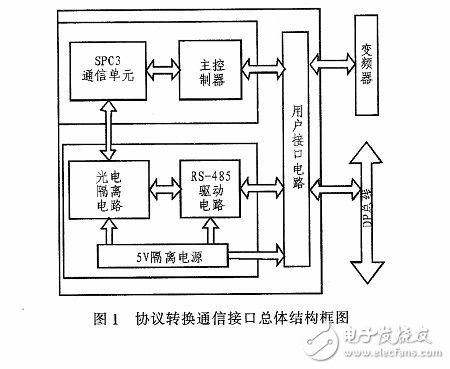
1 Protocol conversion communication interface hardware design 1.1 Protocol conversion communication interface overall structure block diagramFigure 1 is a block diagram of the overall structure of the communication interface between the Profibus-DP and Modbus protocol for the inverter, including the main controller, SPC3 communication unit, optocoupler isolation circuit, RS-485 drive circuit, 5 V isolated power supply, user Interface circuit and corresponding peripheral circuit.
 1.2 Protocol conversion communication interface hardware circuit design
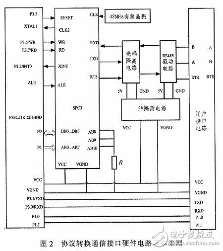
 As shown in Figure 2, the main controller in the protocol conversion unit uses the P89C51RD2HBBD MCU of PHILIPS, which is mainly used to control the DP master station data of the Profibus-DP protocol chip SPC3, and the DP is executed by executing the corresponding protocol conversion program of the P89C51RD2HBBD MCU. The data is converted into Modbus data and sent to the inverter user terminal; the data information returned by the inverter can also be transmitted to the DP master station through the SPC3 communication unit through the user interface circuit; in addition, in the protocol conversion process, there are 4 kinds of inverter terminals. Different baud rates are 19 200bps, 9 600 bps, 4 800 bps, 2 400 bps, and for Profibus-DP, the transmission rate can reach up to 12 Mbps, in order to prevent data loss during transmission. Another important function of the protocol conversion unit is to solve the communication rate mismatch problem between the DP and the Modbus protocol during the conversion process: in order to realize the same transmission rate of the inverter and the main controller, the two I of the main controller The /O port is connected to the inverter through the user interface unit. When the protocol conversion unit starts working, the main controller obtains through this interface. The baud rate selection signal sent by the inverter sets the baud rate of the corresponding asynchronous serial communication accordingly, so that the transmission rate of the inverter and the main controller is the same.
The Profibus-DP protocol chip SPC3 in the protocol conversion unit is a Profibus dedicated communication chip developed by Siemens for intelligent slave stations. The chip integrates a complete DP protocol and can automatically detect the baud rate from 9.6 Kbps to 12 Mbps. Integrated with 1.5KB of RAM. The chip is designed for cyclic MS0 and acyclic MS1 data exchange (ie Profibus DP-V0 and DP-V1). With this chip, only one external device is needed to implement a Profib us site; in this communication interface module, its 8 data buses, 11 address buses and corresponding control buses are respectively associated with the main controller in the protocol conversion unit. In addition, the data transmission signal TXD, the data reception signal RXD and the transmission enable signal RTS of the SPC3 chip are connected to the RS-485 drive circuit; the external clock interface of the SPC3 is available in 24 MHz and 48 MHz, and the design adopts A 48 MHz active crystal provides a clock signal to the SPC3. In addition, SPC3 provides a 12 MHz operating clock to the main controller by dividing the 48 MHz clock signal by four.
The RS-485 communication unit realizes the physical layer function of the DP slave node of the interface communication device, wherein the bus A and B data signal line interfaces adopt a 50 M baud rate in order to avoid interference of the bus signal by the DP slave device. The optocoupler HCPL 7101 is isolated, and the RTS signal line is isolated by a 10 M baud optocoupler HCPL0601. In addition, to prevent the device from being enabled, the RTS signal is high on the bus and causes a bus system error. The HCPL7101 output is inverted first. 74HC132 is connected to the bus; in addition, for the optocoupler isolated power supply, the interface is designed with the chip ADUM5000, the ADUM5000 is a 2.5 kV isolated DC/DC converter chip, the power input is 5 V or 3.3 V, and the output is 5 V or 3.3 V; The input and output of the selected ADUM50 00 in the design are selected to be 5 V. The input power is supplied by the inverter through the user interface, and the isolated 5 V power supply supplies power to the RS-485 drive circuit and the rear stage of the optocoupler.
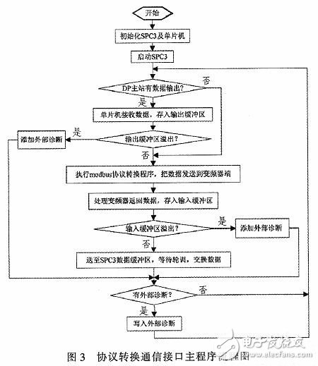
2 protocol conversion communication interface software design 2.1 main program flowAs shown in Figure 3, the main program flow: first initialize SPC3, the DP master station configures the corresponding configuration message and parameter message, and initializes the asynchronous serial communication interface of P89C51RD2HBBD MCU; after SPC3 completes initialization, it can The DP master enters the data exchange state and waits for the master station to send a command. If the master station has data output, the MCU acquires the data into the output data buffer (relative to the master station). If the buffer does not overflow, the Modbus protocol program is called to put the data. The package is in Modbus frame format and transmitted to the inverter through the serial port. If the output buffer overflows, an external diagnosis is generated. When the DP master polls the slave for the next diagnostic message, it is sent to the master station and processed by the master station. After receiving the command sent by the DP master, the inverter returns the response data. The MCU acquires the data through the serial port and stores it in the input data buffer (relative to the master station). If the input buffer does not overflow, it is stored in the SPC3 data. Buffer, waiting for polling, exchanging data with the primary station. If there is an overflow, an external diagnosis is generated. When the DP master polls the slave for the next diagnostic message, it is sent to the master station and processed by the master station.
 2.2 Key Technology Research - Reliability and Real-Time
 In the protocol conversion process, there are 4 different baud rates on the inverter side, which are 19 200 bps, 9 600 bps, 4 800 bps, 2 400 bps, and for Profibus-DP, the transmission rate can reach up to 12 Mbps. The communication rate of the two is not completely matched. In order to prevent the transmitted control command information from being overwritten due to the higher communication speed of the DP master than the inverter, the output double buffer is opened in the P89C51RD2HBBD MCU, that is, the protocol conversion unit receives When the DP master sends data, it is stored in the first buffer. After the data is forwarded to the inverter, the buffer is cleared immediately, and the empty flag of the first buffer is set, waiting for the next data storage. When the next data arrives, first check the empty flag bits of the two buffers, store the data in the buffer that has been emptied, and then send it to the inverter in time through the protocol conversion program, and avoid the data through the double buffer. The possibility of information being overwritten, and at the same time, to prevent the special communication rate in some special cases, such as DP, the data transmission rate of the inverter is set to Low, may cause double buffer overflow and lose the function of avoiding data information being overwritten. The SPC3 communication unit can generate data overflow user diagnostic message and send it to the DP master station. The master station knows the cause of the error by reading the diagnostic information. Handle accordingly. When the data transmission rate of the inverter side is much larger than the baud rate of the DP communication, the input double buffer is opened in the single chip microcomputer, and the reliability and real-time performance of the data transmission of the communication interface are achieved in the same manner.
3 test experiments and results analysisIn order to verify the correctness and rationality of the Profibus-DP and Modbus protocol conversion interface hardware and software designed in this paper, combined with the existing experimental conditions of the laboratory, PLC 300 is used as the DP master station to build an experimental test platform. The test flow is shown in Figure 4. First, the DP master is initialized. When entering the DP master to enter the data exchange state, according to the actual control command of the inverter, the DP master sends a control command frame to the inverter. After receiving the data sent by the DP master station, the conversion interface parses out the actual inverter control command, encapsulates it into Modbus data, and sends it to the inverter. The inverter responds according to the received Modbus data. The data returned by the DP and the Modbus protocol communication interface is converted to the DP frame format and sent to the DP master. At the same time, in order to more intuitively observe the DP data and Modbus data converted by the protocol conversion interface, ProfiTrace is used to monitor the data sent and received by the DP master station. At the same time, the protocol conversion interface sends the obtained Modbus data to the serial port debugging assistant through the serial port. The debugging assistant monitors whether the converted Modbus data is the same as the data exchanged by the DP master, thereby improving the reliability of the test test and further verifying the reliability of the function of the protocol conversion interface. ProfiTrace is a DP data monitoring device, and the data transmitted on the DP bus can be acquired in real time through the corresponding operating software Proficore.
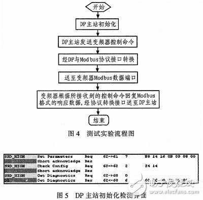
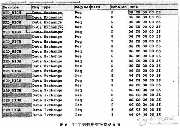
For the initialization of the DP master, as shown in Figure 5, when the DP master completes the parameter message configuration and configuration message configuration, it enters the data exchange phase after obtaining the diagnostic information 00 0C 00 0100 08, as shown in Figure 6. The part circled by the solid line box is the inverter command sent by the DP master station. The part circled by the dotted line box is the response data returned by the inverter back through the DP and Modbus protocol conversion interface. It can be seen through the Proficore monitoring interface. The data output by the DP master and the received data are both 06 C8 00 00 25, where 06 C8 00 00 25 is the control start command sent by the DP master to the inverter, after the inverter receives the control command correctly. Return the received data to the DP master to inform the master that the command data is correctly received.
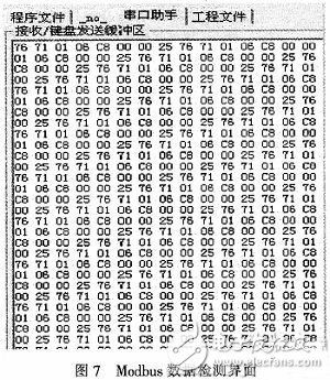
In addition, as shown in Figure 7, the Modbus data converted by the protocol conversion interface obtained by the serial port debugging assistant is 01 06 C8 00 00 25 76 71, a total of 8 bytes, where 01 is the address defined by the inverter, and 76 71 is Modbus. The CRC of the data, 06 C8 00 00 25 is the actual data portion, which is consistent with the data sent and received by the DP master.
Since the Profibus-DP communication rate can reach up to 12 Mbps, four different baud rates are defined for the inverter side, namely 19 200 bps, 9600 bps, 4 800 bps, 2 400 bps, in order to verify the protocol conversion interface at different communication rates. The correctness and reliability of the down-converted data are set by the DP master station and the protocol conversion day to set the communication rate of different frequencies. After the above experiment, the communication interface is tested multiple times to ensure the correct data transmission.
4 ConclusionIn summary, the protocol conversion communication interface is an integrated Profibus-DP intelligent slave interface on a circuit board, and embedded DP data and Modbus data conversion function, so that the inverter using Modbus RTU protocol communication can Master station communication using the Profibus-DP protocol. In terms of hardware, the P89C51RD2HBBD+SPC3 ​​protocol chip + RS485 driver circuit can realize the conversion between Modbus protocol and Profibus-DP protocol, and physical connection with the inverter through the user interface; in software, according to the four types of control of the inverter Command: Control the inverter to start and stop, read the current status of the inverter, set the inverter parameters and read the inverter parameters. The DP master converts the control commands into the corresponding DP frame format data and sends them to the DP slave node of the device. After the controller acquires the data through the SPC3 communication unit, it is packaged into Modbus data, and is sent to the inverter by using the asynchronous serial interface of the single-chip microcomputer to achieve the purpose of controlling the frequency converter. Similarly, the inverter returns corresponding according to the received control command. Data information, the main controller obtains through the user interface circuit, and extracts valid data to send it to the output buffer of the SPC3 protocol chip, periodically exchanges data with the DP master station, and in addition, realizes communication between the inverter and the DP master station. Rate matching, by opening a 5-byte double buffer in the internal controller of the main controller, through the SPC3 pass on the main controller When the unit receives the DP master data, it first judges the empty flag bits of the two buffers, stores the data in the buffer with the empty flag bit 0, and after clearing the buffer to the inverter after the protocol conversion processing, immediately clears the buffer and corresponding The empty flag bit waits for the next data transmission. At the same time, to ensure the security and reliability of the protocol conversion, if the double buffer overflows, the overflow diagnostic message is generated by the SPC3 communication unit and returned to the DP master. Make the appropriate processing.
Compared with the prior art, this design provides a communication interface device for protocol conversion between Modbus and Profibus-DP for the inverter using Modbus RTU protocol. Through experimental verification, the software and hardware of the communication interface are designed correctly, and the inverter using Modbus RTU protocol can communicate with the DP master station, and the data conversion is real-time and reliable. To a certain extent, this communication interface has expanded its application range for inverters using Modbus protocol communication, which has important practical significance.
Our coin handling machines mainly include Coin Counting Machine, Coin Sorting Machine and Coin Sachet Machine
Coin counting machine models: HCS-3300, HCS-3500AH, CS-10S, CS-2000
Coin sorting machine models: CS-211S, CS-311S, CS-610S+PRO, CS-910S+, CS-600B, CS-211S, CS-311S, CS-610S+PRO and CS-910S+ have alloy sensor for counterfeit detection, CS-600B sorts coin by diameter
Coin sachet machine: pack the loosed coins into small plastic bag, compared with paper roll packing machine, it is more economic solution
Coin Counter Counting Euro Coins,Coin Counter For Vending,Coin Counter Super Large Hopper,Super Heavy Duty High Speed Counter
Suzhou Ribao Technology Co. Ltd. , https://www.ribaoeurope.com