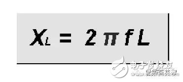
According to the following capacitive reactance formula
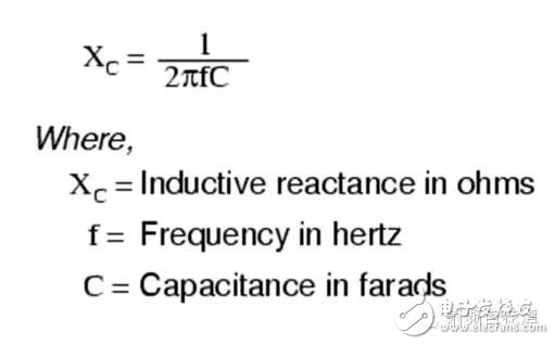
The frequency is 0 is open circuit, so as long as the string capacitance can block DC regardless of the capacitance value, then the above formula also knows that the larger the capacitance value, the smaller the capacitive reactance, that is, the smaller the Loss, and the larger the capacitance value is, the more the RF signal is. The closer it is to the 0 ohm resistance, and the 0 ohm theoretically does not change the RF impedance, so a conclusion is reached. In theory, a large capacitor can be used not only as a DC block but also as an RF impedance.
2. Why are all pF levels? It is reasonable to say that the capacitance of the nF level is smaller. Why not?The junction of the RF trace and the capacitor is an impedance discontinuity as shown below:

In general, the larger the value of the capacitor, the larger the size of the junction, and the more the impedance offset will be at the junction. This will lose the above effect of "not affecting the impedance of the RF". In other words, you will have a large size. Although the capacitance is very small, the capacitance is very small, but it is likely that the Loss caused by the impedance offset is still larger. Since 100 pF can do things, why use a 3.9 nF to increase the trouble? ? ? Look at Loss, not just see InserTIon Loss, but also consider Mismatch Loss.
3. That assumption is also the size of 0402. Why can you only use the pF level?All materials in the 0402 size capacitor can reach the nF level and some can even reach the uF level.
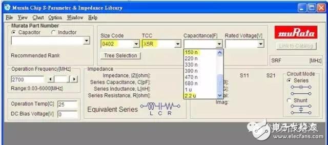
4. But among these materials, only C0G (or NP0) capacitors have the highest stability.
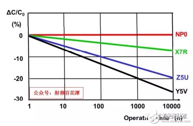
Time stability:
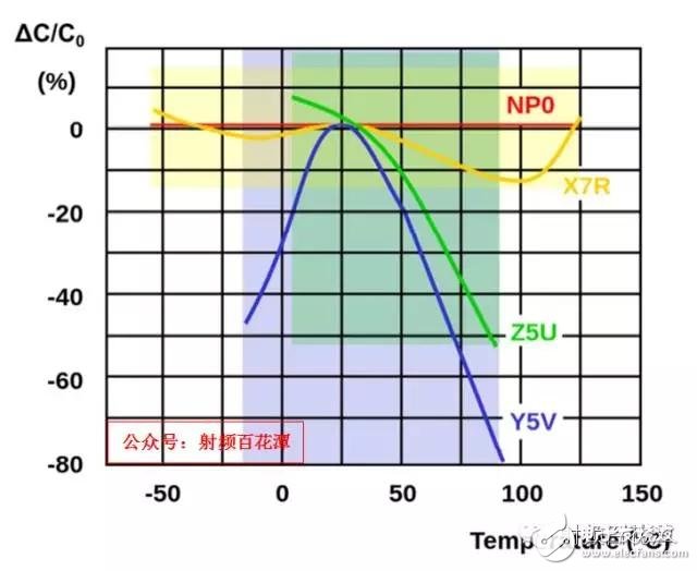
Temperature stability:
5. Frequency stability:
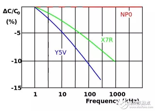
6. In other words, only the capacitor of C0G (NP0) has a capacitance value that does not vary with time, temperature, and frequency. Therefore, in RF applications, only C0G (NP0) material is preferred. Others are not good choices, but C0G (NP0) The capacitance of the material is only up to 1nF, so most of them can only use the pF level.

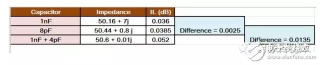
7. Assume that the same 0402 size is also C0G (NP0) material, and there is also a maximum of 1nF. Can only use pF level? First compare IL (InserTIon Loss) Assume that the RF frequency is 2700 MHz for LTE Band 7, and the IL for 1nF is 0.036 dB.
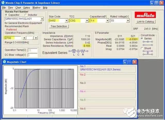
8. The IL of 8pF is 0.0385 dB, and the 8pF of IL is indeed larger because the smaller the capacitance value, the larger the ESR is. Of course, the IL is larger, so the difference between 1nF and 8pF is mainly due to the difference of ESR, but then A 0.036 dB to a 0.0385 dB, in fact, there is no big difference, do not need to calculate the difference of 0.0025 dB.
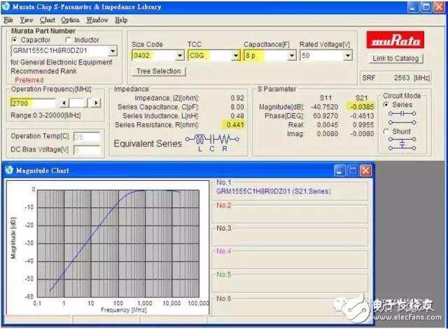
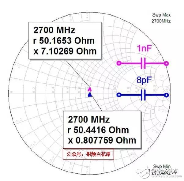
9. However, the degree of impedance offset is different. Suppose the original impedance is 50 ohms. As shown in the figure above, the impedance deviation of 1nF is larger than 8pF, which loses the DC Block. The role of the impedance, in other words, if the RF trace impedance is well controlled, the trace is short enough, in principle, 8pF is used. When the DC Block has a impedance of 50 ohms, there is no need to adjust the impedance to restore the overall impedance to 50 ohms. However, if 1nF is used, the impedance of the DC Block will deviate from 50 ohms, and an additional re-matching is required to restore the overall impedance to 50 ohms.
10. Therefore, if 1nF is used, DC block needs to be connected in series with a 4pF capacitor to restore the overall impedance to 50 ohms.
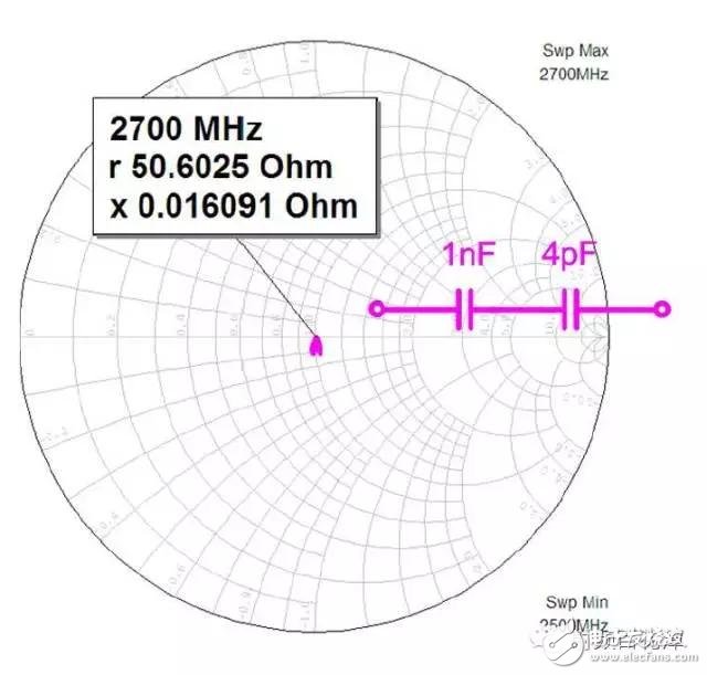
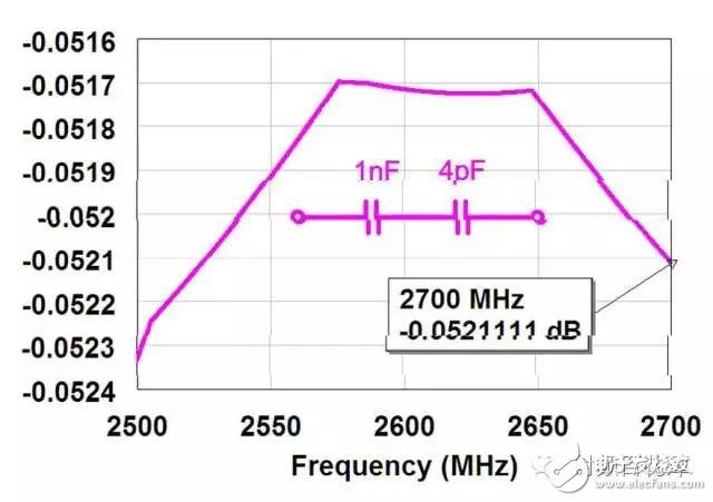
11. Let's take a look at the IL after a series of 4pF capacitors.
12. So the arrangement is as follows:
This means that you want to save the 025dB IL and discard 8pF and use 1nF DC Block. As a result, you need to add 4pF capacitor to restore 50 ohm impedance. In other words, not only the extra time and workload of the matching match. At the same time, there is an extra IL of 0.0135 dB. Is this transaction worthwhile? ? As long as the series passive components are inductors, capacitors, or resistors, because of their internal resistance, they will additionally contribute IL. Therefore, unless necessary, the series components can be added without adding them. In this principle, 8pF is of course compared with 1nF. Is the preferred DC Block option
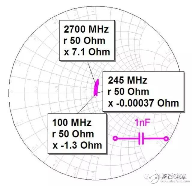
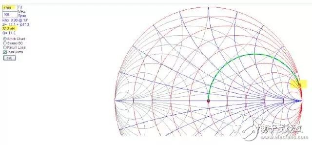
13. According to the first point, the larger the capacitance value, the closer it is to 0. The impedance of the ohm should be smaller. In theory, 1nF should be closer to 0 ohm. Is the impedance offset greater than 8pF? How can I run to the right? Is that a trace of string inductance? This is the first point where the ideal component is the case, but the real capacitor will have SRF with 1nF and 8pF SRF as shown below:
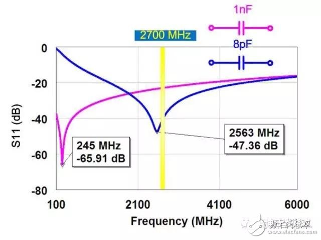
By the way, SRF is connected in series. It depends on S11. The parallel SRF is S21. It can be seen from the above figure that the 8pF SRF is closer to the RF frequency of 2700 MHz, so the impedance offset is smaller. Otherwise, the 1nF SRF is farther away from the RF frequency of 2700. Therefore, the degree of impedance offset is large, so the degree of impedance offset is not determined by the capacitance value but by the difference between the RF frequency and the capacitance SRF, because the SRF of the pF level capacitor is closer to the RF band. Smaller,
14. Therefore, using the pF level on the RF path, the impedance of the DC Block will be less offset, which is in line with the DC Block "and does not affect the RF impedance". This is why the DC on the RF path. Block is mostly pF level. In addition, the reason why the string of 1nF capacitor will run to the right as the inductor is SRF. The above figure shows that the 1nF capacitor has SRF of 245 MHz. Therefore, its behavior pattern is as follows:

SRF (245 MHz) is the watershed. If the signal frequency is located on the left side of the SRF, it is the capacitive mode whose trajectory will run to the right. If the signal frequency is exactly at the SRF, it is the resistance mode and its trajectory is almost motionless (because of the internal resistance). Very small is not enough to affect the impedance). If the signal frequency is located on the right side of the SRF, it is the inductive mode and its trajectory will run to the right.
15. As shown below:
So this is why the string of 1nF capacitors will run to the right as the inductor, because the RF frequency (2700MHz) is located on the right side of the SRF. In this case, the inductor mode, so the trajectory of the 8pF capacitor is actually running slightly to the right. Because the 8pF capacitor has an SRF of 2563 MHz, its RF frequency is located on the right side of its SRF. In this case, it is inductive mode. It is also known that the true capacitance, no matter how large, is exactly equal to 0 when the signal frequency is exactly SRF. The ohmic resistance, as long as the signal frequency is not equal to the SRF, its behavior mode is one of the inductive mode and the capacitive mode.
16. Therefore, verify again why the DC block on the RF path is mostly pF level, because only the pF level capacitor can make the RF frequency beside the SRF to show the capacitance mode instead of the inductive mode because this is equivalent to When the capacitor is used as an inductor, it becomes a DC Blocking inductor at this time. It does not mean that there must be a hazard. If it can be avoided, try to avoid it.
17. Why are the inductors all nH rated?
In general, the series connection of the inductors on the RF path is used for matching according to the inductive reactance formula:
The larger the inductance value, the larger the inductive reactance is, the larger the IL is. Therefore, if the series inductance value is small, the smaller the better, the better, to reduce the IL. In addition, the larger the series inductance value, the more the impedance shifts. Figure:
In other words, if a large series inductor is needed for matching, it means that the original impedance of the PCB trace is very far from 50 ohms, but basically if the impedance is controlled, the original impedance of the PCB trace will not be 50 ohms. Too far, so there is no need for large series inductance in the RF path.
Why do you need to increase IL?
18. In addition to this, the inductor has the same SRF as the capacitor. Its behavior is as follows:

The same is the SRF as the watershed. If the signal frequency is located on the left side of the SRF, it is the inductance mode. The trajectory will run to the right. If the signal frequency is exactly at the SRF, it is the resistance mode. The trajectory is almost motionless (because the internal resistance is not enough) Influencing the impedance), if the signal frequency is located on the right side of the SRF, then the capacitance mode will traverse down to the right, so verify again why the series inductance on the RF path is mostly nH level, because only the nH level inductance can make the RF frequency It is located on the left side of its SRF to show the inductive mode. At this time, the impedance trajectory predicts that the matching will be smoother. Otherwise, due to the parasitic effect of the PCB trace and the stacked structure, the impedance trajectory has been simulated. The prediction has some error. If the impedance trajectory of the component itself is difficult to predict the string inductance but runs to the lower right, this will make the impedance trajectory of the network component have more error with the simulation prediction, which is not as good as the blind adjustment.
19. At the same time, verify again that the capacitance on the RF path is mostly pF level, because only the pF level capacitor can make the RF frequency appear on the left side of the SRF to exhibit the capacitance mode, so that the impedance trajectory is predicted when matching.
Blouses And Shirts,White Cotton Blouse,Cute Blouses For Women,Long Sleeve Tops Women
GUANGZHOU LIWEI ELECTRONICS CO.,LTD , https://www.gdliwei.com