Recently, sophisticated battery-powered electronic systems and self-powered devices have extended some different applications in the field of existing autonomous handheld devices. Significant advances in CMOS processing technology and circuit technology have reduced the power consumption of the circuit, making the new autonomous power supply system possible. These advances have led to a number of emerging applications such as wireless microsensor networks, wearable medical electronics, industrial and home automation sensors and electronic shelf labels. Ideally, these systems will work without a battery. However, when batteries are required, we still need to try to extend battery life so that the system does not need to be replaced during its life cycle. Understanding the workings of an energy converter and how it can be used to provide energy is a basic requirement to achieve these goals.
Self-powered systems require an energy source to maintain normal operation over their life cycle. Commercial energy converters can be divided into the following four categories based on different energy sources:
1) Light: The solar cell consists of a pn crystal array that works with the photovoltaic effect.
2) Heat: Collect thermal energy using thermoelectric components.
3) Vibration: The vibration energy harvester uses the mechanical energy of vibration by electromagnetic or piezoelectric methods to generate electrical energy.
4) Radio waves: Radio wave energy harvesting methods are more effective when using directional solutions, but there is not much useful power in realizing the use of ambient energy.
Table 1 Typical output power of the energy harvester

Table 1 shows typical power levels from different energy converters and important considerations for the collector. In general, most collectors provide an average power of around ~10-50 μW/cm2. The amount of power obtained is related to the collector area and is heavily dependent on the available space of the collector. Using a solar cell example, we can describe some of the characteristics of the collector. The solar cell can be modeled as a current source in parallel with the diode, as shown in Figure 1. The shunt resistor models the leakage and the series resistor models the contact cell resistance.
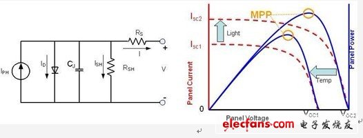
Figure 1 Electrical model of photovoltaic cells and their characteristic curves
When the light hits the solar cell, the battery produces a current IPH that flows through the output. When the battery is open, this current forms a voltage VOC at the output. The battery generates power between the extremes of open and short circuit. In Figure 1, the red curve shows the current vs. voltage characteristics of the solar cell. The illuminance increases, the short-circuit current increases, and the battery open circuit voltage is slightly affected. The power obtained from a solar cell reaches a maximum at a certain voltage and then gradually drops at either end of the voltage. This is the maximum power point of the battery. It is related to incident light and other environmental factors such as temperature. Other converters have similar maximum power point (MPP) characteristics due to their high impedance characteristics. Therefore, how to choose a power management solution to work under MPP is a key factor we need to consider.
A thermoelectric generator (TEG) is used to collect ambient heat and generate a voltage according to the Seebeck effect "1". The basic building block of the thermal collector is a thermocouple. This thermocouple consists of an n-type material in series with a p-type material. When a temperature difference occurs in this material, heat begins to flow from the high temperature surface to the low temperature surface. Heat can move free electrons and holes and form an electric potential. Commonly used thermal collectors consist of p and n doped antimony telluride because of their excellent thermal properties. A pn pin of this material creates a temperature difference of approximately 0.2 mV/K between the hot and cold faces.
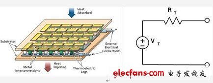
Figure 2 Thermopile array and simple TEG electrical model
To increase the output voltage and get more power (see Figure 2), we electrically connected many pins in series and thermally in parallel to form a thermopile capable of producing a temperature difference of about 25 mV/K. This thermal energy collector can be modeled as a voltage source in series with the same resistance, and its open circuit voltage is proportional to the temperature difference. The resistance comes from the resistance of the metal interconnect and the edge of the pellet. From this model, we can easily know that to extract the maximum function, the impedance needs to be controlled to match the load from the generator. An important aspect of thermal energy harvesters is that they require a proper heat flow system around them to maintain heat flux and good temperature differentials. If the heat balance is allowed on both sides of the TEG, the electrical power output reaches zero.
A common method of collecting environmental mechanical energy is to utilize piezoelectric components. The input vibration experienced by the piezoelectric material shown in Figure 3 causes mechanical strain in the device and is then converted to electrical charge. The equivalent circuit of the PE collector can be represented as a mechanical spring mass system that is coupled to an electrical domain. Looking closely at the resonant frequency of the device, we can transform the entire circuit into an electrical domain [2]. Thus, when excited by a sinusoidal vibration, the piezoelectric component can be modeled as a sinusoidal current source in parallel with capacitor CP and resistor RP.
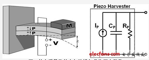
Figure 3 Piezoelectric components loaded with a mass and its electrical modeling
In addition, we can also use electromagnetic collectors to collect mechanical energy, which uses magnetic energy to generate electricity using kinetic energy. In order to maximize power output, the collector needs to be fine-tuned to the optimum resonant frequency of the application environment and the rectified impedance is adjusted to match 2. Compared to piezoelectric collectors, the adjustment of these devices is simpler and it is easy to get the desired power output. However, both of these mechanical energy converters have resonances themselves and have a narrow operating frequency band.
in conclusion
In short, it is important to understand the characteristics of the energy converter. Only by understanding their characteristics can energy conversion be optimized to create a viable energy harvesting system. Some important considerations for energy converter power management include energy source properties, energy converter characteristics, and power management performance. Matching the power management solution to get the maximum output power from the converter and store it efficiently requires us to understand the important parameters above. It helps us develop an energy harvesting system with the best performance to better serve the target application.
Solar energy system, off gird pv system, grid pv system, solar power system, Solar Panel system, on grid solar system, grid tied solar system,20kw solar system
Solar energy system include Solar photovoltaic system: 1. Off grid photovoltaic system mainly consists of solar modules, controllers, and batteries. To supply power to AC loads, it is also necessary to configure an AC inverter. 2. Grid connected photovoltaic power generation system. 3. Distributed photovoltaic power generation system. Distributed power generation or distributed energy supply.
solar cell type
mono crystalline, half cut cell
solar energy pv system include
on grid system, off grid system, hybrid system
solar configuration
solar panel, inverter, battery, bracket cabels, mc4 connector
Product details and pic


Solar Engergy System,Gird Solar Power System,Pv System For Carport,Energy System Off Grid Solar System
PLIER(Suzhou) Photovoltaic Technology Co., Ltd. , https://www.pliersolarpanel.com