Most large embedded systems are powered by a 48V input that is sent through the backplane to each PC board in the system. This type of power supply is often referred to as a distributed power system. The 48V input is reduced to a lower voltage by an isolated intermediate bus converter (IBC), typically in the 5V to 12V range. Then, this intermediate bus output voltage needs to be lowered again for the branch circuit and the IC on the board. These branch circuits and ICs require tens of milliamps to tens of amps of current and 0.8V and higher. These devices that complete the buck again are called point-of-load (POL) regulators.
Distributed power systems typically include a microprocessor and a digital signal processor (DSP), both of which require core power and input/output (I/O) power supplies that must be ordered during startup and shutdown. Designers must consider the relative size of the core and I/O voltages and the timing of the voltage during power up and power down to meet the manufacturer's performance specifications. If there is no proper power sequencing, latching or excessive current sinking can occur, which can result in microprocessor I/O ports or supporting devices (such as memory, programmable logic devices, field programmable gate arrays, data converters, etc.) Damage to the I/O port. To ensure that the core voltage is properly biased before driving the I/O load, it is necessary to track the core supply voltage and the I/O supply voltage.
Some processors require that the I/O voltage rise before the core voltage, while some DSPs require the core voltage to rise before the I/O voltage. Power sequencing is also required. An application specific integrated circuit (ASIC) with up to seven input voltage rails that need to be ordered is common. The ideal sorting allows for arbitrary sorting of all tracks in the system, allowing any rail to be lifted depending on the other rails. A dependency is established between these rails so that if one of the rails does not rise to full voltage when power is applied sequentially, the power up process stops. In addition, in FPGAs, PLDs, DSPs, and microprocessors, diodes are typically placed as electrostatic discharge (ESD) components between the core and the I/O supply. If the input voltage is not controlled, or if the power supply cannot supply the pre-biased load, these internal diodes may be damaged when power is applied or powered down.
In the case of a pre-biased load, a voltage has been applied to the load, which may be a steady state voltage or a voltage that begins to change from power up or power down. ASIC is a good example of an IC that can be pre-biased. In general, an ASIC would require multiple voltage rails to operate at, for example, 1.0V, 1.1V, 1.2V, 1.8V, 2.5V, and 3.3V. Inside the ASIC, there is a diode between these rails that protects the internals by not allowing a voltage higher than the voltage across the diode. When powering up or powering down, there may be a situation where the voltage between the two rails in the ASIC is much higher than the diode voltage drop, causing a large current to flow through the diode and causing the diode to fail. This large current can flow back into the synchronous MOSFET of the DC/DC converter, and this usually happens when power is applied or powered down. This problem can be prevented by using a DC/DC converter that does not allow negative current to flow through the output inductor when it is turned on or off. This method requires the DC/DC converter to burst when powering up or powering down. Mode (Burst Mode) or discontinuous conduction mode works.
A new way to solve old problemsLinear Technology's DC/DC converters safely power pre-biased loads. The recently introduced three-output, multi-phase synchronous DC/DC controller, the LTC3853, is one such DC/DC converter. The LTC3853 is a high efficiency, three output synchronous step-down switching regulator controller with consistent or proportional tracking capability. Power sequencing is very easy to achieve with an accurate run threshold and two power good outputs. Its 4.5V to 24V (28V maximum) input range covers a wide range of applications, including most intermediate bus voltages. A powerful internal gate driver powers all N-channel MOSFET stages, and each phase can be generated with an output voltage range of 0.8V to 13.5V in one channel and an output voltage range of 0.8V to 5.5V in the other two channels. More than 20A of output current. The constant frequency architecture allows for an optional fixed or synchronizable phase-locked loop (PLL) frequency from 250kHz to 750kHz.
The LTC3853 is configured as three separate outputs and can also be configured as a 2 + 1 controller. In this case, channel 1 and channel 2 can be connected to make the two outputs in parallel, and channel 3 is a separate output. By operating the three output stages with a phase difference of 120°, power and power supply noise are minimized. When configured as a 2 + 1 type controller, channel 1 and channel 2 are 180° out of phase, maintaining an optimal balance of input current when there is a large current output and a small current output.
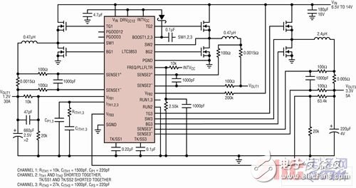
Dual output converter operating in 2 + 1 modeFigure 1 shows the schematic of a dual output converter operating in the 6.5V to 14V input range. Channel 1 and Channel 2 feed the same 1.2V output, while Channel 3 controls the second 3.3V output. This 2 + 1 configuration requires only one RUN pin (RUN1) to start Channel 1 and Channel 2. The feedback error amplifier for channel 2 is disabled and the two channels share the feedback divider of channel 1. The post-package trim of the current sense comparator provides excellent current sharing between channel 1 and channel 2. This is illustrated in Figure 2, which shows the inductor current for each channel with a ±25% load step, resulting in an output voltage transient of approximately 63mVpp, less than ±3%.
Programmable Power Meter,Network Power Analyser,Remote Terminal Unit,Smart Gateway
Jiangsu Acrel Electrical Manufacturing Co., LTD. , https://www.acrel.com.pk