As shown in the figure, the hepatitis sterilizer control circuit. The control circuit is composed of a step-down rectifier circuit, a single stable time circuit, a relay control circuit and the like. The buck rectifier circuit provides a DC voltage to the entire control circuit.
555 and W1, R1, C1 and double-layer button AN constitute a boot trigger timing circuit. When using, just press AN, transformer B will be powered, and 555 will be set because the potential of 2 feet is low. The high level of output of 3 feet makes relay J suck, contact J1-1 is closed, power supply The voltage is self-locking closed. Thereafter, C1 is charged by W1 and R1. When charging to 2/3VDD, 555 is reset, the low level of the 3-pin output causes relay J to be released, and contact J1-1 is turned off. The power supply voltage is cut off. The delay time td=1.1 (Rw1+R1)C1 of the corresponding 555 is the disinfection timing time, and the length can be changed by adjusting W1.
Since 40 g of the refined salt is dissolved in 1000 g of water during the disinfection, electrolysis is performed to produce a strong oxidizing agent HCLO, NaCLO, etc. which are harmless to the human body, and they have a strong killing effect on hepatitis*, Escherichia coli and the like. This control circuit is used to control the timing of generating NaCLO.
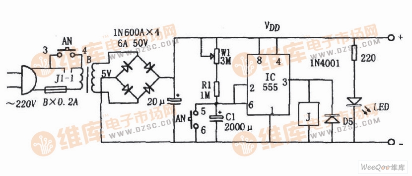
Hepatitis bactericidal control circuit diagram composed of 555
The 555 circuit contains two voltage comparators, a basic RS flip-flop and a discharge switch T. The comparator's reference voltage is provided by a voltage divider consisting of three 5K resistors. They make the non-inverting input of the high-level comparator A1 and the inverting of the low-level comparator A2, and the reference levels of the input terminals are 2/3VCC and 1/3VCC, respectively. The outputs of A1 and A2 control the state of the RS flip-flop and the state of the discharge tube switch. When the input signal is from the 6 pin, that is, the high level triggers the input and exceeds the reference level 2/3VCC, the flip-flop resets, the output of the 555 pin 3 outputs a low level, and the discharge switch tube is turned on; when the input signal is from 2 The input of the pin is lower than 1/3VCC, the trigger is reset, the 3 pin of 555 outputs high level, and the discharge switch tube is cut off. RD is the reset terminal (4 pins). When RD=0, 555 outputs a low level. Usually the RD end is open or connected to VCC.
Our company specializes in the production and sales of all kinds of terminals, copper terminals, nose wire ears, cold pressed terminals, copper joints, but also according to customer requirements for customization and production, our raw materials are produced and sold by ourselves, we have their own raw materials processing plant, high purity T2 copper, quality and quantity, come to me to order it!
Copper Connecting Terminals,Cable Lugs Insulated Cord End Terminals,Pvc Insulated Cord End Terminal,Cable Connector Insulated Cord End Terminal
Taixing Longyi Terminals Co.,Ltd. , https://www.longyicopperterminals.com