Principles of TV scanning technology
Television technology uses the principle of photoelectric conversion to transform optical images into television signals. This conversion process is usually done in the camera. When the subject is imaged by the camera lens on the photoconductive layer of the camera tube, different points on the photoelectric target excite a different number of photoelectrons depending on the illuminance, thereby causing different additional photoconductors to generate different potential fluctuations, forming a light image. Corresponding electrical image.
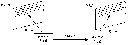
Using the visual inertia of the human eye, the physical quantity of the pixels in the representative image can be transmitted one by one in a certain order at the transmitting end, and the original image is reproduced again at the receiving end according to the same law. As long as this sequence is fast enough, the human eye will feel that the image is shining at the same time. In television technology, the established law of transmitting images is called scanning. As shown in Fig. 07-02-5, the electrical image formed in the photoconductive layer of the camera tube sequentially turns on each point under the scanning of the electron beam, and continuously converts their brightness changes into electrical signals; After the electrical signal is transmitted through a single channel, the electron beam is used to scan the screen with electro-optic conversion characteristics, and the electrical signal is converted into an optical image.

Figure 07-02-5 TV system scanning principle
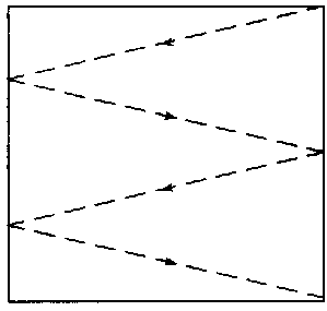
Under normal circumstances, the current electric vacuum imaging and imaging devices commonly used in television systems use electron beam scanning to realize photoelectric and electro-optical conversion; and with the use of CCD cameras and flat panel display devices, various pulse digital circuits are utilized. The above conversion can be achieved. Figure 07-02-6 is a schematic diagram of a cathode ray tube (CRT) scanning process in which a video signal is composed of luma and chroma signal components, which respectively deliver luminance and chrominance signals.

Figure 07-02-6 Schematic diagram of cathode ray tube (CRT) scanning process
There are two types of scanning methods: progressive scanning and interlaced scanning.
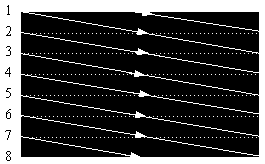
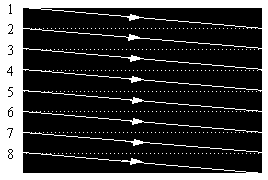
The manner in which the electron beams are sequentially scanned from left to right and from top to bottom is called progressive scanning. The linear bright spot trajectory formed by the electron beam sequential scanning screen is called a grating, and the schematic diagram of the grating formed by progressive scanning is shown in Fig. 07-02-7.
(1) Line scanning: The scanning of the electron beam in the horizontal direction is called line scanning. The scan from left to right is called the line scan forward, which is referred to as the line sweep, as shown by the solid line in Figure 07-02-7(a). The right-to-left scan is called the line scan reverse, which is called line retrace. This is shown by the dotted line in Figure 07-02-7(a). The line scan has a long forward stroke time and a short reverse stroke time. Obviously, for each image, the more scan lines, the higher the resolution of the image, the finer the image; but at the same time, the wider the bandwidth of the TV signal, the higher the requirements on the channel.
(2) Frame scanning: Scanning of the electron beam in the vertical direction is called frame scanning. The scan from top to bottom is called the frame scan forward range, which is referred to as frame scan, and the bottom-up scan is called frame scan reverse, which is called frame retrace. Figure 07-02-7(a) shows the scan path of the frame scan forward, and Figure 07-02-7(b) shows the retrace path of the frame scan reverse. Similarly, the frame scan forward time is much longer than the frame scan return time.
In fact, the line scan and the frame scan are performed simultaneously, that is, the electron beam moves in the vertical direction L while scanning in the horizontal direction, and the motion trajectory of the electron beam is a combined motion in both the horizontal and vertical directions. Since the scanning speed of the electron beam in the horizontal direction is much larger than the speed in the vertical direction, a horizontally bright line which is slightly obliquely downward is formed on the fluorescent screen, and several hundred lines of dense scanning bright lines form a uniform grid-like luminous surface, which is called Raster. One frame scan is a field.
|
|
(a) | (b) |
Figure 07-02-7 Schematic diagram of progressive scan raster
The disadvantage of progressive scanning is that if the image is continuous without flickering, it is necessary to change the frame 50 times per second, that is, the frame frequency is 50 Hz, but the bandwidth of the image signal is too wide, which complicates the television device. In order to compress the bandwidth of the image signal and overcome the flicker phenomenon, the interlaced scanning method has been proposed by referring to the film technology. Current broadcast television uses interlaced scanning.
2. Interlaced scanning
Interlaced scanning is to scan one frame of image into two fields. The first field sweeps odd rows, called odd fields, and the second field sweeps even rows is called even fields. The odd and even field images are mosaicd together to form a complete image, as shown in Figure 07-02-8.

Figure 07-02-8 Interlaced image reproduction image
The interlaced raster is shown in Figure 07-02-9. After the electron beam sweeps the first line, it returns to the position starting from the third line and then sweeps, as shown in Figure 07-02-9(a), then at the 5th. , 7, ..., the line sweeps until the last line. After the odd lines are scanned, the even lines are scanned (Fig. 07-02-9(b)), thus completing a frame scan (Fig. 07-02-9(c)). It can be seen that an image of one frame of interlaced scanning is composed of two parts: one part is composed of odd lines, which is called odd field, and the other part is composed of even lines, which is called even field, and two occasions form a frame. Therefore, in interlaced scanning, whether it is a camera or a monitor, acquiring or displaying an image must be scanned twice to obtain a complete image (Fig. 07-02-8).

(a) odd field (b) even field

(c) one frame of interlaced scanning
Figure 07-02-9 Interlaced raster diagram
In interlaced scanning, the number of lines scanned must be an odd number. As described above, one frame of picture is divided into two fields, the first field scans half of the total number of lines, and the second field scans the other half of the total number of lines. Interlaced scanning requires that the first field end in half of the last line. Regardless of how the electron beam is folded back, it must return to the center of the top of the display, thus ensuring that the adjacent second field scan is exactly embedded in the first field. intermediate. It is for this reason that the total number of rows must be odd.
Interlaced scanning is required to scan 50 fields per second in order to make the moving image have a continuous feeling without flickering, that is, the field frequency is 50 Hz. When two fields are one frame, 25 frames per second are scanned, that is, the frame rate is 25 Hz, thereby reducing the frame rate, compressing the image signal bandwidth, and overcoming the flicker phenomenon.
How many lines are scanned per second is called the line frequency fH; how many fields are scanned per second is called the field frequency fc; how many frames are scanned per second is called the frame rate fF. Fc and fF are two different concepts.
Both black and white televisions and color televisions use interlaced scanning, and computers typically use non-interlaced scanning when displaying images.
Detachable Power Cord,Fuse Power Cord,Ac Power Cord
Ningbo Aurich Electronics Co.,Ltd , http://www.powercordset.com

