Abstract: This paper introduces a 250W metal halide lamp electronic ballast. The circuit consists of PFC, Buck converter and full-bridge inverter. In order to avoid acoustic resonance, the full-bridge inverter operates at a low-frequency square wave of 200 Hz, and on this basis systematically studies the dynamic and steady-state characteristics of the metal halide lamp.
Key words: electronic ballast; metal halide lamp; acoustic resonance
1 Introduction
At present, metal halide lamps have been widely used in many lighting fields due to their high luminous efficiency, good color rendering and long life. However, due to the non-linearity of its volt-ampere characteristics, ballasts are required for start-up and arc-discharge.
Gas discharge lamps, especially metal halide lamps, have acoustic resonance problems when operating at high frequencies, which can lead to instability of the arc, changes in color temperature, and even arcs. The main methods to overcome acoustic resonance are:
1) The gas discharge lamp is operated at extremely high frequency [2], which exceeds the frequency range of the acoustic resonance, but since the switching loss is proportional to the switching frequency, the heat dissipation and efficiency problems become abnormal;
2) The gas discharge lamp is operated in the frequency modulation state [3], so that the acoustic resonance cannot be formed, but the gas discharge lamps produced by various manufacturers are not the same in appearance, and the frequency band of the silent resonance is also different, so it is also difficult;
3) The gas discharge lamp is operated in a low frequency square wave, and the frequency band of the acoustic resonance is generally in the range of several kHz to 1 MHz, so the acoustic resonance is generally not formed.
In this paper, a three-stage electronic ballast is used, which works in the low-frequency square wave mode and adopts constant power control, which avoids the problem that the lamp voltage rises with the aging of the bulb caused by the constant current control method.
2 circuit topology
The 250W electronic ballast described in this paper is shown in Figure 1. It is developed for the US power grid standard, so the input voltage is 120 V AC. In order to achieve a higher power factor, the first stage power factor correction circuit (PFC) converts 120V AC to 240 V DC, the second stage DC/DC converter is used for constant power control, and the Level 3 DC/AC inverter will The DC is converted to a 200 Hz square wave voltage. Since the metal halide lamp requires an ignition voltage of 2 to 3 kV, a single-stage igniter is added to generate a high voltage pulse. The constant power control samples the output voltage and current of the Buck converter (level 2 DC/DC) to control the PWM drive signal of the Buck converter.
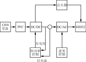
Figure 1 Electronic ballast block diagram
3 circuit working principle
The first stage circuit is shown in Figure 2. It consists of an EMI filter and a PFC circuit. The PFC circuit is controlled by the MC34262 chip, and a power factor close to 1 can be obtained. It converts the AC 120V into 240V DC and is used as the input of the next-stage DC/DC converter.
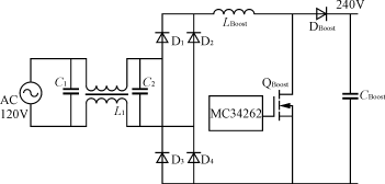
Figure 2 Level 1 PFC main circuit
The main circuits of the 2nd and 3rd stages are shown in Fig. 3, which are respectively composed of a Buck converter and a full bridge inverter circuit. Before the metal halide lamp starts to rise, the current is detected as zero due to the open load of the load. Buck controls the maximum duty cycle of the output. The output of the Buck circuit is about 240V. It is charged to C3 via R3 and is charged to the trigger voltage of the bidirectional trigger tube (SIDAC). When the trigger tube is turned on, C3 is discharged, the high voltage is applied to the primary side of the step-up transformer T1, and the secondary side outputs a high-voltage pulse of 2 to 3 kV, which is applied to both ends of the metal halide lamp to provide the ignition voltage thereof, if one ignition fails. C3 is charged again, repeating the above process until the metal halide lamp is lit. When the metal halide lamp lights up and the current increases, the output of the Buck converter will drop. The steady-state operating point is about 120V, which is lower than the trigger voltage of the SIDAC. It does not generate high-voltage pulses. When the bulb is broken, it does not need to be turned off. When the power is turned off, you can re-light it by replacing it with a new one.
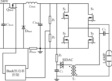
Figure 3 2nd and 3rd stage main circuits
4 Experimental results and analysis
A 250W electronic ballast prototype verifies the above scheme. The component parameters are as follows: LBoost=180μH, CBoost=400μF, LBuck=120μH, CBuck=1μF, RSense=0.1Ω, R1=200kΩ, R2=256Ω, R3=100kΩ, C3 =1 μF, T1 åŒ ratio = 1:20. Figure 4 shows the voltage waveform across C3. It can be seen that the trigger frequency of SIDAC is 3.6Hz, which is about 280ms. When the SIDAC triggers conduction, the secondary side induces a high voltage pulse. The waveform is as shown in Figure 5, and the peak voltage reaches 2kV.
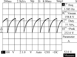
Figure 4 Voltage across C3
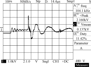
Figure 5 Voltage when the lamp is ignited at both ends
1) Dynamic characteristics
Figure 6 shows the change in voltage and current during the entire process from start-up to steady state. From this, we can see the control process of constant power. It takes about 150 seconds for the lamp to start from steady state to steady state. Figure 7 and Figure 8 show the lamp voltage and lamp current as a function of time. The lamp voltage gradually increases with time. On the contrary, the lamp current decreases slowly with time. The metal halide lamp undergoes four stages during the startup process: gas ionization phase, glow discharge phase, glow discharge to arc discharge transition phase, and arc discharge sustain boost phase. Fig. 9 is a graph showing the variation of the lamp equivalent resistance with time. Since the lamp resistance is nonlinear, constant power control is used.
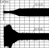
Figure 6 lamp voltage, current dynamic process
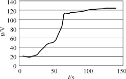
Figure 7 lamp voltage-time curve
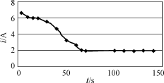
Figure 8 lamp current-time curve
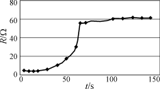
Figure 9 lamp resistance-time curve
2) Steady state characteristics
Figure 10 is a steady state voltage and current waveform of the lamp. It can be seen that the voltage and current are in phase, the voltage and current are linear, and the power factor is close to 1, so the metal halide lamp can be regarded as a resistor in steady state, and the 250W metal halide lamp is about 62Ω.
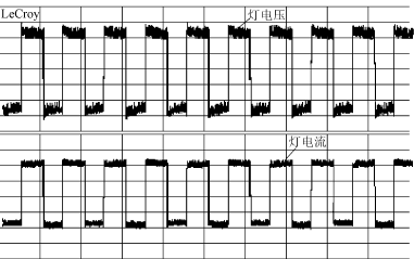
Figure 10 Steady-state voltage and current waveforms across the lamp
5 Conclusion
The experimental research shows that the three-level electronic ballast described in this paper has the characteristics of high reliability and good stability, and the starting circuit is simple and practical. The steady-state and dynamic characteristics of the 250W metal halide lamp are also given.
Yuhai company develop and produce of various rings sizes, bearing variety of electrode and metallisation configurations. This variety of Rings is fabricated from various material formulations for applications such as high power, sensitivity, stability.
Features
· • electrode type on request
· • Surface roughness on request, for specific demanding application
· • Thickness/Radial frequency tuning available on request
• Wide choice of PZT formulations
Applications include
• Sensors
• Welding
• Ultrasonic cleaning
• Precise Measurement
• Ultrasonic scalpel
• Cauterisation
• Phacoemulsification
• Therapeutic ultrasound
• Accelerometers
Dimension range
|
Outer diameter |
3-180mm |
|
Inner diameter |
1-150mm |
|
Thickness |
0.2-25mm |
Piezo Ring,Pzt Ring,Piezoelectric Ceramic Ring,Piezo Ceramic Ring
Zibo Yuhai Electronic Ceramic Co., Ltd. , https://www.yhpiezo.com