When evaluating ripple, it is usually done around the two components of ripple voltage and ripple current.
In most applications, ripple is a state of circuit that engineers want to minimize. For example, in an AC-DC converter that converts AC power to a stable DC output, efforts are made to avoid a phenomenon in which the AC power source is superimposed on the DC output with a small, frequency-dependent change signal.
However, in other cases, the ripple can be a necessary design function, for example, a clock signal or a digital signal can utilize a change in voltage level to switch the state of the device.
In the latter case, the consideration of corrugation can be said to be quite simple: do not let the peak voltage exceed the rated voltage of the capacitor. However, it is important to keep in mind that the peak voltage is the sum of the highest ripple voltage and the DC bias voltage in the circuit. In addition, there is another special consideration for electrolytic capacitors using bismuth, aluminum and tantalum oxide technologies: Do not let the minimum value of the ripple voltage fall below zero potential, as this will cause the capacitor to work in the opposite direction. To the bias condition. This requirement also applies to Class II ceramic capacitors for low frequency applications.
Capacitors act as charge banks, and when the voltage increases, they are charged; when the voltage drops, they discharge to the load; they essentially act as smooth signals. The capacitor will experience a varying voltage and, depending on the applied power source, may also have varying currents, as well as continuous and intermittent pulsating power. Regardless of the input form, the change experienced by the capacitive electric field will cause the dipole in the dielectric material to oscillate, thereby generating heat. This reaction behavior, called self-heating, is one of the main reasons why dielectric performance is an important indicator because any parasitic resistance (ESR) or inductance (ESL) will increase energy consumption.
Dielectrics with low losses (ie low ESR/DF and low ESL) will generate less heat than high ESR and DF dielectrics; however, these parameters also vary with frequency because different dielectric materials provide optimum performance in different frequency ranges ( That is, the least heat is).
The capacitor dielectric is very thin, and it may only be a small part of the total mass of the capacitor, so other materials used in the structure should also be considered when evaluating the ripple. For example, a capacitor plate in a non-polar capacitor (such as a ceramic or film capacitor) is metallic; a polar capacitor (such as tantalum or aluminum) has a metal anode (in the tantalum oxide technology, the anode is a conductive oxide) And a semiconductor cathode (such as manganese dioxide or a conductive polymer). On external connections or pins, there are various conductive contacts, including metals (such as: copper, nickel, silver, palladium, and tin) and conductive epoxy. When AC signals or currents pass through these materials, they will have A certain degree of fever.
To understand how these factors work, let's take the example of using a solid tantalum capacitor to smooth the residual AC ripple current at the DC output stage. First, since this is a polarity technique, a positive voltage bias is required to prevent the AC component from causing a reverse bias condition. This bias voltage is typically the rated output voltage of the power supply.
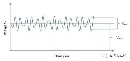
Figure 1: The ripple voltage is superimposed on the bias voltage. (Voltage: Voltage Time: Time)
Before we consider ripple, we must pay attention to the heat generated by the applied DC bias. Capacitance is not an ideal device. A parasitic phenomenon is a shunt resistor that spans a dielectric material that will cause leakage current (DCL) to occur. This small DC current can cause heat, but unlike other typical applications, the heat is usually negligible. A 100uF/10V SMD tantalum capacitor has a DCL of no more than 10uA (100uA@85°C) at room temperature, so its maximum power consumption is 1mW.
Next, we look at the power dissipation due to the ripple value of the current at a given frequency (equal to "R", the ESR of the capacitor at the same frequency) (equal to I2R, where "I" is the current rms [rms]) .
We start by examining a sinusoidal ripple current and its RMS equivalent. If at a certain frequency, we make a 1A Irms current through a 100mΩ ESR capacitor, the power consumption is 100mW. Continuous power supply, based on the thermal capacity of the capacitive component structure and packaging material, and all measures taken to dissipate heat to the surroundings (eg, a combination of convection, conduction, and radiation), this current will cause the capacitor to heat up internally until it reaches the surrounding environment balance. In this case, the ripple heat is 100 times that of the DC leakage current, so the latter (as mentioned above) is negligible. However, when evaluating a new capacitor, it is always a good idea to check for DC leakage current heating.
After defining a number of factors that determine the self-heating caused by the applied ripple, we can now set a limit. Although, "How big is the ripple is too big?" There is almost no fixed answer to this question, just like the answer to the question "How long is the rope?" Therefore, the standard method is to set only an arbitrary temperature change, and Using this as a reference point, it is backwards to estimate how much ripple is needed for a given capacitor to cause this change.
Generally, depending on the capacitor technology, it is recommended to select +10°C or +20°C as the maximum temperature increment tolerance. Use the following reference conditions to calculate the ripple required to produce the above conditions:
1) ambient temperature of 25 ° C; 2) ripple is a continuous sine wave, and its frequency corresponds to the ESR test frequency of the capacitor; 3) "free space" (ie, no heat sink or forced cooling, and free to at least Capacitance in five orientations [other orientations may be soldered to the test board] for thermal radiation); 4) Also, in the case of a polar capacitor, a DC bias is applied to ensure that the associated ripple voltage does not occur on the capacitor Any reverse voltage.
Then, the ripple current is increased and the device temperature is monitored until it reaches equilibrium at its recommended temperature tolerance point T above ambient temperature.
The measured Irms is often cited as a ripple current limit, but it is not a practical limitation in terms of maximum voltage scaling or maximum ESR limits; in fact, it is a best practice condition that can be used as a basis for application evaluation.
This measurement also allows calculation of the power dissipation and thermal resistance of the capacitor. The power consumption "P" is given by:

Where: "R" is the ESR of the capacitor at the ripple frequency, and the thermal impedance is the amount of heat generated per unit time and temperature in °C/W.
From the above, we can see that for a given capacitor, power consumption is a function of frequency (due to ESR). The thermal impedance (in this case, empirically measured) can also be calculated based on the mass of the capacitor and the heat capacity of its constituent materials. However, the environmental conditions of the capacitor (ie, the thermal management of the system) have the same effect on the heat generation of the capacitor in the application.
The thermal impedance is the same for capacitors of the same volume and composition. Therefore, if ESR is known, the power consumption per unit time of each nominal parameter capacitor of the same product series can be calculated, and the expected temperature rise can also be calculated by multiplying the thermal resistance by the power consumption.
Returning to the ripple current measurement, this value will immediately indicate if the selected nominal value can be used for a given application. To fine tune this value to match the actual ripple conditions, the manufacturer gives data on typical ESR versus frequency and ESR versus temperature so that the ESR can match the application conditions. This information is usually given in the nominal value item in the data sheet and is also available in software that allows the user to change the frequency and temperature. If the ripple is non-sinusoidal, non-continuous, or intermittent (eg, pulsed discharge), the designer will need to use an appropriate transformation method to calculate the rms equivalent or use the peak as the worst case.
Next, the system can be thermally modeled with all of the strong cooling or cooling measures that reduce the temperature of the capacitor. In addition, if there are other heat-generating devices next to the capacitor, the temperature may increase. .
If there is not enough data for either of these two methods of heat dissipation, then the often most accurate empirical method can be used. As long as the circuit is operated in the worst condition and the temperature of the device is raised to ambient temperature by means of a thermocouple or pyrometer.
The first thing to confirm is that the equilibrium temperature should not be higher than the maximum operating temperature of the capacitor, and the associated peak ripple voltage (plus any applied bias voltage) does not exceed the maximum operating voltage. For many capacitor technologies, as the temperature increases, the ESR decreases, so the effect of ESR on ripple heat is reduced. However, it is not counted in the supplier's data sheet, nor is it required (if the device is actually measured in the application).

Figure 2: Thermal model of the tantalum capacitor.
Lead frame: leadframe Solder: Solder tantalum anode: tantalum anode printed circuit board: PCB encapsulant: sealing materials copper: Copper
If the device is operating within the limits of all operating parameters, there is no problem; for critical applications, the actual reliability of the capacitor can always be recalculated based on its actual maximum temperature, not the ambient temperature of the circuit. If the calculated or measured temperature rises above the recommended operating range, the device may still be operational (if the above conditions are met), but should still communicate with the supplier to confirm whether additional considerations should be considered in this case. pressure.
After determining which factors affect fever, let's take a look at some practical applications.For low voltage (eg 1.8V~5.5V rail) DC applications, high capacitance chip multilayer ceramic capacitors (MLCC) and solid tantalum electrolytic capacitors are preferred for DC power supply filter capacitors in the 10kHz to 10MHz range. . These technologies are capable of providing hundreds of microfarads (uF) of capacitance values ​​at low voltage levels in small sizes. The temperature characteristics of the X5R chip multilayer ceramic capacitors support a particularly high capacitance value with a typical ESR in the range of 1 to 10 mΩ but with an upper temperature limit of 85 °C. Although the capacitance value of the X5R device is maximized for the low voltage level, one of the characteristics of these capacitors is that the capacitance value decreases with the applied voltage (voltage coefficient), and the capacitance value decreases with the increase of the operating temperature. Small (temperature coefficient).
However, its ESR remains low, so the ripple current capability will not be affected. In applications where low bulk capacitance losses are preferred, the X7R temperature characteristics can be used. For a given size and voltage rating, the X7R's nominal capacitance is lower than the X5R MLCC, but the effect of the voltage coefficient is reduced (and further reduced if voltage derating is used), and when the operating temperature is extended to 125 In the °C range, the temperature coefficient will also be more stringent.
Solid tantalum electrolytic capacitors are polar devices that require a DC bias in ripple applications and provide very high capacitance values ​​in the range of 100μf to 1mF; their typical ESR is an order of magnitude higher than MLCC. Therefore, replacing tantalum capacitors with tantalum oxide capacitors is a worthwhile solution. The solid electrolytic capacitor uses a base metal as a base anode material (i.e., a positive electrode side capacitor plate), is coated with a ruthenium pentoxide dielectric, and uses manganese dioxide or a polymer film as a negative electrode material (i.e., a negative electrode side capacitor plate).
The tantalum oxide capacitor is provided with a conductive NbO anode and a tantalum pentoxide dielectric.铌 is the same family element, but the density is lower. They are processed in a similar manner and have similar electrical properties; however, germanium dielectrics are more robust for any given voltage rating. This means that for the same voltage class, the electric field stress during operation is smaller and more reliable, but it also limits its maximum rated voltage and slightly increases its ESR. However, in corrugation applications, the small difference in ESR is compensated by the higher specific heat and lower thermal impedance of the tantalum material. This means that bismuth and antimony oxides with similar indices have similar ripple properties.
At low ripple frequencies, the typical ESR of X5R or X7R (Class II Dielectric) MLCC increases faster than 钽 or 铌. Therefore, the latter is more favored by audio applications, but due to excessive self-heating, neither is used for low frequency applications (eg, line applications below 100 Hz). When using larger stacked ceramic capacitors for switch mode applications, the manufacturer's software typically alerts when low frequency, self-heating or ripple voltage itself is out of limits, and may not apply DC voltage due to the use of Class II ceramics. Offset to get another warning.
The dielectric structure of a class II ceramic capacitor can be thought of as a collection of domains with internal dipoles that vary with the applied AC voltage. However, if there is no DC offset for compensation, the various domains will flip when subjected to a reverse voltage, thereby increasing internal heating. Therefore, for low frequency applications, a lower dielectric constant (ie, a lower capacitance value for a given size and voltage/capacitance value combination), a larger size, or a stack of multiple capacitive elements (eg, cascading) may be required. Class I dielectrics such as NP0/C0G are generally a better choice for ceramic capacitors in switch mode.
For large-film capacitors used in DC link applications ranging from 500uF to 1mF/450V to 1kV (typical for automotive inverters), the ripple current will cause the device to heat up, but its mass is high. It means that the thermal time constant needs to be considered. In fact, in some cases, in corrugated applications, it may take an hour or so for the capacitor to reach equilibrium temperature. Polypropylene is generally the preferred dielectric because of its extremely low power consumption and low heat generation due to large ripple currents. Such capacitors typically have custom specifications for specific vehicle and/or inverter applications.
For example, all film capacitors have an inherent self-healing mechanism, but this self-healing mechanism can be enhanced by using a special structure within the metal electrode system so that the total capacitive surface area can be divided into parallel multiple micro-components to prevent short circuits. malfunction. Over time, high temperatures and applied voltages reduce the capacitance value, but if the free/bus time of the application is known, the actual capacitance value and the nominal value can be accurately calculated and considered in the initial design.
In short, ripple is generally the state of the circuit you want to avoid. However, in some applications it can also be an effective design feature.
Ring Type Connecting Terminals
Ring Type Connecting Terminals,Terminals,Connecting Terminals
Taixing Longyi Terminals Co.,Ltd. , https://www.lycopperlugs.com