In the initial development stage, the TV set only supported the playback and display of monochrome (ie black and white) images. With the development of technology, color TV broadcasting is also supported, but the backward compatibility of black and white TV display devices still needs to be maintained. TVs need to contain color information within the available bandwidth and continue to display distortion-free black and white pictures in the same format as earlier TVs.
In a composite video signal, the color information and the available brightness information share the same bandwidth. Sinusoidal waves of different amplitudes and phases represent the chromatic content of any transmitted image (Figure 1). Therefore, it is necessary to separate chrominance and brightness in order to display the picture correctly.

Figure 1: Luminance and chrominance information share the same frequency spectrum of a composite video signal.
The chrominance information is placed at the high end of the spectrum and is a multiple of the line length. The display problem is how to correctly extract the brightness and chrominance information, and how to maintain full bandwidth without causing display artifacts.
If no luminance-chrominance separation occurs, the color information makes the picture brighter or darker when the carrier is circulating or reversed. At the same time, the color information will also appear in the black and white part of the image by mistake (Figure 2).

Figure 2: Images without brightness and chrominance contain a lot of artifacts.
Using a simple notch filter or band-pass filter to separate the luminance and chrominance will result in chrominance residuals in the luma signal path and luma residuals in the chroma signal path (Figure 3). Residual information can cause serious image artifacts, such as "dot creep" (Figure 4). The residual chromaticity information in the chromaticity path can also cause artifacts such as "cross-color" (Figure 5).
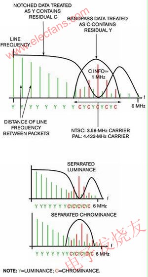
Figure 3: Using a notch filter or bandpass filter to separate brightness and chroma.
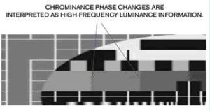
Figure 4: The TV mistakenly interprets the residual color in the brightness path as brightness information, causing an undesirable point creep effect.
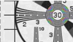
Figure 5: The residual luminance signal in the chroma path causes cross-color artifacts.
The signal delay function of the comb filter itself causes constructive interference and destructive interference. The frequency response of the comb filter consists of a series of evenly spaced spikes, in the shape of a comb. Compared with notch filters and band-pass filters, 2D comb filters can provide higher video decoder performance (Figure 6).
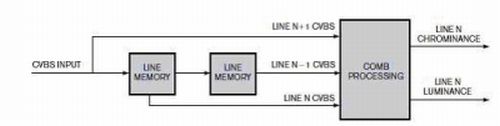
Figure 6: The three-row 2D comb filter will use input-output one-line delay.
The working principle of the 2D comb filter is that if there are similar lines above and below the target line of the image, the chrominance and brightness can be more completely separated.
Under the NTSC (National Television System Committee) system, the chromatic sine wave signal changes 180 ° line by line. Adding any two consecutive lines will double the brightness content and cancel the chrominance content. Conversely, if two lines are subtracted, the luma content cancels out and the chroma content doubles. For example, for the full-screen color bar, each active line is visually the same. At a given signal level, the brightness content of each line is the same. In addition to the phase change, the chroma content of each line is the same.
The video decoder (such as ADI's decoder) uses a five-line 2D comb filter, which can provide better performance for NTSC and PAL (progressive phase inversion) signal sources. Depending on the complexity of the image, the comb processor must determine whether to combine the current line with the next or previous line.
The comb processor cannot arbitrarily combine certain images, and can cut into the current line. The adaptive 2D comb video decoder can provide an acceptable level of performance. However, when the consecutive lines are different, the 2D comb filter does not work properly and turns to the notch filter to separate the brightness and chroma of the line area.
Although it is important to successfully achieve brightness and chrominance separation without image artifacts or bandwidth limitations (which translates to low-contrast images), there are many other aspects of video signals, such as poor timing or non-standard weak radio Signals also bring many challenges.
The acceptable artifacts or image defects of small CRT displays are unacceptable for the new generation of plasma displays and liquid crystal displays. Because as the resolution increases, the size and contrast of the display increase, even small image defects will become apparent.
Adaptive 3D comb filter technology
High-definition (HD) signal source, digital interface and high-resolution display can bring excellent visual experience. However, through channel switching or input, the user may see beautiful high-definition images or traditional composite video broadcasting (CVBS). With the help of high-quality adaptive 3D comb filter technology, the quality of standard definition (SD) composite video images has been significantly improved (Figure 7).
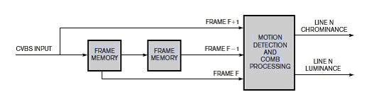
Figure 7: Typical architecture of a decoder with a built-in 3D comb filter.
A 3D comb filter is similar to a 2D comb filter, which separates brightness and chroma by combining pixels in certain rows. The main difference between the two is that the 2D comb filter combines the pixels of successive lines of the image, while the 3D comb filter combines the pixels of the current line with the pixels in the same line in the image delay state (Figure 8).
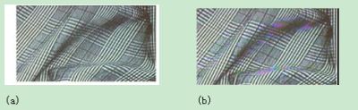
Figure 8: The result of adaptive decoder with built-in 3D comb filter (a) is significantly better than the decoder with built-in 2D comb filter (b).
The 3D comb video decoding scheme can provide excellent video quality. This method can fundamentally eliminate bad image artifacts, such as point creep, "hanging points" and cross color.
In addition, thanks to the brightness and chrominance separation method of 3D comb video decoding, this method can maintain the full bandwidth of the brightness and chrominance packets.
The full-luminance bandwidth retains high-frequency content and provides clear and sharp images, allowing users to distinguish minute details. The full chroma bandwidth ensures brighter and clearer colors.
2D comb video decoding mainly processes adjacent active video lines for analysis, or both processing and analysis, while 3D comb processing compares frame-to-frame video pixel information (Figure 9). It compares the current frame data with the previous frame data in memory.
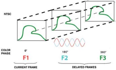
Figure 9: The typical frame sequence of NTSC format shows the 3D comb filtering technology.
If two frames are added at the same time, the chrominance information of each pixel cancels, and the luminance pixel data doubles. Similarly, if the previous frame is subtracted from the current frame, the luma pixel data is cancelled, and the chroma information is doubled.
Despite the many advantages of 3D comb filter processing, designers must still address their performance limitations and challenges. The 3D comb filter can perfectly separate the brightness and chroma of the image, but the traditional 2D comb filter or notch filter can not achieve this effect.
However, only when the pixels in the image are absolutely still can the perfect separation of brightness and chroma be achieved. Conversely, if the image is moving and the pixel data of two consecutive frames is changing, the 3D comb filter cannot be used (Figure 10). It is important that the video decoder examines each pixel and compares it with the previously stored pixel data to determine whether any movement has occurred and then decide which comb filter should be used.
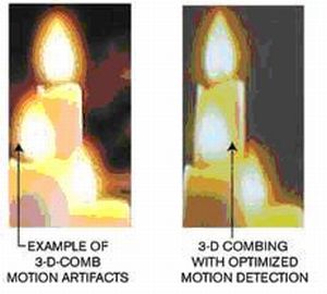
Figure 10: Comb filtering of moving images produces noticeable artifacts.
Due to the complexity of motion detection, the method used must be able to analyze each active pixel of the current and stored frames in order to determine which method to use to separate the information.
The 3D comb filter technology combs still pixels, the 2D comb filter technology processes areas without complex motion, and the notch filter handles complex motion areas. The main challenge of the 3D comb decoder is not the 3D combing process itself, but the complex motion detection and adaptive switching between the 3D comb filter, 2D comb filter and notch filter.
When the comb filter is not competent
The adaptive 3D comb filter relies on the decoder to correctly detect image movement. Otherwise, the comb filter cannot process the pixel data correctly, causing motion artifacts (Figure 11). In Figure 11a the bird's wings are down. In Figure 11b the wings have danced upwards, while in Figure 11c the wings are downward again. This is the normal sequence of birds dancing their wings.
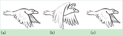
Figure 11: The adaptive 3D comb filter relies on the decoder to correctly detect image movement. This is the normal sequence of birds dancing their wings-downward (a), upward (b), and downward (c).
Many 3D comb decoders check frame 1 and frame 3, and find that frame 1 and frame 3 are the same, and mistakenly believe that there is no image movement. So decided to use 3D comb decoder to process the data (Figure 12).

Figure 12: Using a 3D comb decoder, invalid detection causes significant grid artifacts (a). After image movement correction, no mesh artifacts are generated (b).
In contrast, high-performance video decoders equipped with 3D comb filters use many frame memories to more accurately detect motion between all frames. Using a large number of frames is necessary to help the decoder accurately determine when and where to use the 3D comb filter.
Realize more functions
The 3D comb filter should work normally, and the memory buffer needs to store video pixel data frames for analysis and processing. ADI's 12-bit SD / HD TV video decoder ADV7802 and other decoders are equipped with 3D comb filters and graphics-to-digital converters. By processing other non-3D comb filter tasks, such as advanced timing noise reduction, the maximum Limit the use of memory space.
Equipped with a 3D comb filter, the ADV7802 uses a variety of techniques to compare the pixel data of the current frame with previously stored data, thereby filtering and eliminating image noise.
The external memory can also realize advanced time base correction. Frame-based time-base correction ensures that the decoder always outputs a fixed clock, a fixed number of samples per line, a constant number of lines per frame, and the correct field order.
Although TV applications generally do not require external memory, more and more manufacturers are transferring more receivers and electronic control devices to separate remote control boxes to minimize the thickness of the display panel. However, this type of design also limits the number of cables that need to be connected directly to the TV, which may cause wiring difficulties (Figure 13).
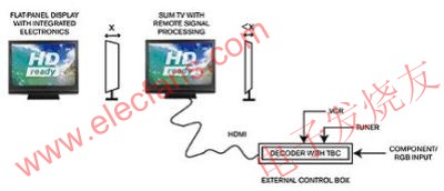
Figure 13: The thin display panel transfers the receiver and electronic control equipment to separate units.
The remote control box is connected to the display via HDMI (High Definition Multimedia Interface) or similar link. When the link is working, the TV needs stable pixel and clock data. Because the time base correction allows the video decoder and the link's transmitting device to be directly connected, the decoder can even provide reliable timing and pixel data for non-standard input devices.
In addition to the separation of brightness and chrominance, many other aspects of composite video processing also directly affect picture quality. The performance of the ADC input plays a decisive role in the overall video quality received by the display.
Professional-quality video decoders (such as the ADV7802) use a 12-bit ADC to achieve a signal-to-noise ratio better than 62dB. It is worth noting that for performance-critical applications, the differential phase shift and gain can exceed 0.45 ° and 0.45%, respectively. Cost-sensitive applications can use a video decoder with a 9-bit ADC, such as the ADV7180 from Analog Devices.
The decoder must also be able to handle non-standard and weak broadcast sources. TV users and manufacturers still attach great importance to these requirements. Consumers who have just bought a new high-end large-screen plasma or LCD TV may also connect it to a 12-year-old video recorder and analog RF cable system.
Consumers used to connect VCRs to old CRT TVs, but now they expect high-definition TVs to bring at least the same level of performance as old CRT TVs. In other words, the video of the recorder should be stable, and it can continue to remain locked even in the "trick" mode (that is, when paused, fast forwarded, or rewinded).
The weak RF signal should also be synchronized with the color lock, even if the input signal drops below 25dBμV. To solve the problems caused by low-level RF signals and video signals and old non-standard systems, decoder designers face many challenges.
When determining the benchmark of the decoder's quality level, the algorithm to be used requires careful consideration. Many manufacturers have promoted that they can successfully handle these signal sources. For example, ADI ’s video decoder integrates technologies such as simultaneous detection and extraction, resampling, and advanced back-end FIFO management.
For example, the intelligent filtering algorithm in the ADV7802 uses a phase-locked loop (PLL) module, as well as horizontal synchronization (HSYNC) and vertical synchronization (VSYNC) processor modules to ensure the correct extraction of synchronization information. This filter ensures that the decoder can identify when it is looking for synchronization information. The synchronous phase-locked loop module and the processor module ensure that the detected synchronization information is correctly arranged.
It applies to the horizontal and vertical low-power wind generator of 100W to 600W. This type Controller has strong compatibility and a great various protection functions, have more 10 years of application practice to improve performance continuously to make it has high reliable and stability. It can be used to the street lighting, monitoring system, outdoor advertisement, home type generation system etc.
Wind Turbine Controller,Motor Controller,Automatic Control Controller,Charge Controller
Delight Eco Energy Supplies Co., Ltd. , https://www.cndelight.com