Its impedance is 300Ω, which is considered to be a high-impedance earphone. Although the sound pressure also reaches a certain level when it is driven by the amp output interface of the CD player, the driving power is too small. When the volume is turned on, the distortion is large and the sound is not It's hard to listen to and cannot play the high-quality characteristics of HD600, so I decided to make a headphone amplifier myself.
In the past few years, I have also made several different tube amplifiers. I just compared the listening experience. I think the sound of the tube amplifier is more beautiful than the transistor amplifier, so the headphone amplifier is also going to be made with a tube. After watching the production experience of some headphone enthusiasts on the Internet and studying many different types of tube headphone amplifier circuits, and then considering my own tube inventory, I decided to choose a tube headphone amplifier designed by Morgan Jones.
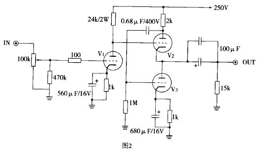
Circuit principle The circuit schematic diagram is shown in Figure 1. It is an output-less transformer (OTL) circuit, without loop feedback, the circuit is very simple, very suitable for imitation of primary headphone enthusiasts. This headphone amplifier only uses one type of 6N1 dual triode tube, and the left and right dual channels share 3 6N1 tubes. 6N1 has a good parameter curve, the social stock is large, and the price is not high, which is conducive to reducing costs. Although the sound characteristics and characteristics will be different, 6N1 can be compatible with and interchangeable with 6N11 (6922, 6DJ8, ECC82, E88CC) in principle. Of course, if 6N11 is used, the relevant components of the line and the screen pressure should be changed accordingly, Figure 2 It is the headphone amplifier made by 6N11 tube for reference by interested friends.
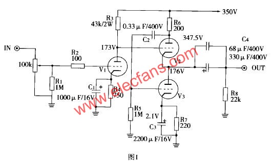
Here I use 6N1T (super-grade) electron tube produced by Beijing Electron Tube Factory. The biggest feature of this 6N1 OTL amplifier circuit is the use of asymmetric output. It is actually similar to the circuit of the popular Hetian Maoshi amplifier some time ago. It removes the line input stage of the Hetian Maoshi amplifier. The signal passes the 100k volume. After the control potentiometer controls the input to the gate of V1, its screen-yin output enables various impedances, especially high-impedance headphones, to have more ample volume output. However, the 6N1's OTL output may not perform as well as it drives high-impedance headphones. Since its final stage uses an asymmetric output like SRPP, a higher voltage power supply is required. Figure 3 shows the power supply.
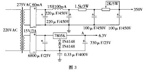
In the author's experience, the simple circuit must have good sound effects, and the power supply part must work hard. The power supply of this headphone amplifier made by the author is not complicated, but the filtering effect is very good. The high voltage part adopts classic π-type LC line filtering, and then performs RC filtering through two resistors, which has good noise reduction characteristics. The high voltage of the line is 350V, and the voltage between the cathode and the filament exceeds the 6N1 specification by no more than 100V. I use a 0.33uF / 400V CBB capacitor to suspend the filament power supply and ground, so that the entire line is The ground connection is through this ground capacitor. The output part of the high-voltage power supply has a 1.5kΩ / 3W and a 2kΩ / 5w variable resistor in series, and the output voltage can be adjusted by adjusting the resistance of the 2kΩ / 5w variable resistor when in use. The filament power supply here uses a 7805K metal shell three-terminal regulator as the DC power supply after rectification; at the same time, the 9th pin of 6N1 is the shielding layer of the two vacuum transistors located in the electron tube, and it should be grounded when used , Not only can reduce the hum, but also help to reduce the mutual interference of the two vacuum transistors.
Production and adjustment The chassis uses an aluminum chassis, the transformer and the electronic tube are installed on the upper part of the chassis, and the internal wiring of the chassis. The AC power socket and audio input socket are placed on the back of the bottom plate, and the power switch, headphone socket, and volume control components are installed on the front of the bottom plate. Among them, the input socket and volume control are as far away as possible from the power supply part and the power switch. In order to achieve a good sound effect, the resistance used in the audio line of this machine is 1 / 2W American DALE resistor, high-power resistors use high-quality metal film resistors, the input volume control uses Japanese ALPS 100K blue plastic shell varieties, C1 and C3 are Japanese ELNA supplement high-speed electrolysis, C4 uses German WlMA polypropylene capacitors, the sound is clear and bright, with French SOLEN is more softer, the output capacitor here is Philips 330uF / 400V electrolysis and 68uF / 400V SOLEN poly Acrylic capacitors are formed in parallel. It has been proven that this connection not only improves the sound quality, but also does not increase the cost significantly.
The transformer uses a 60W R-type transformer with low magnetic leakage and high efficiency, which is beneficial to improve the sound quality. The voltage of the secondary high-voltage coil of the transformer should be between 265V and 280V, the current should be greater than 50mA, and the voltage of the low-voltage coil should not be less than 10V. Since each 6N1 filament current reaches 0.6A, three 6N1 filaments are provided With electricity, the current capacity of the low-voltage coil should be greater than 2A. The line is covered by a shed. Each ground point connects the total ground wire (12AWG solid copper wire) to the bottom plate of the fixed place with a star ground. The bottom plate is polished with sand cloth to ensure a reliable grounding. If conditions permit, R-type transformers and 15H choke inductors are best packaged in a grounded metal box to reduce interference to surrounding circuits.
Before powering on, test whether the power supply of the amplifier is normal. If there is no load, the power supply voltage will rise a lot (about 400V). Therefore, it is best to plug in the electron tube when testing the power supply voltage. Before plugging in the electron tube, you should check whether the welding is correct. , Is there any virtual welding and so on. When adjusting the high-voltage power supply voltage, the resistance of the parallel resistance 2k / 5W can be changed, and the adjustment voltage is about 350V. When testing the filament voltage, the electronic tube is also required to be installed in the socket. If it is no-load, the voltage at point A should be between 6.5 and 7V. After the electronic tube is installed in the socket, the voltage at point A should be between 6.1 and 6.5V.
Whether the line is normal should check the voltage value of each point on the circuit diagram 1. For the 6N1 circuit, I measured the contact voltage between R3 and V1 as 173V, the contact voltage between R6 and V2 as 347.5V, the positive electrode of the output capacitor has a voltage of 176V, and the voltage of 1.2V is on the cathode of V1. In this case, the voltage measurement values ​​at these points will be slightly different, and there may be a slight difference between the two channels of L and R, which are allowed. If these checks are normal, you can prepare to start listening.
The sound quality of this headphone amplifier after careful adjustment is quite solid when playing CD, and the signal to noise ratio is very high, and the background is quiet. The stereoscopic image and clarified transparent sound emitted by the orchestra when listening to "Chopin Piano Concerto No. 2" appeared very realistic through the HD600. I have heard this CD many times, but the headphones still bring me extraordinary Feelings. After "burning" for nearly a week, the tone is soft and vivid, the high and low frequencies extend smoothly, the tone is fluctuating, the changes are rich, and the low frequencies are full of subtle texture changes, especially the piano touch keys are beautiful and rich and full of vitality, the sound does not have ordinary transistor ears The thinness of the display is full of energy and movement, and the three-dimensional performance is also excellent.
The capacitance used by this machine has a great influence on the sound. Please use high-quality products when possible. The output electrolytic capacitor C4 is electrolyzed with German ROE supplements, and the sound is unique compared to Philips electrolysis. Of course, if there are conditions, the components of the left and right channels, especially the electronic tubes, should be paired and used as much as possible to reduce the difference in voltage measurement values ​​of the points of the left and right channels. In this way, the stereo effect and sound image localization of the sound effect will be more accurate, and the sound will be Smoother and more intense rhythm.
In general, this amp is very loud even when the volume is turned on, and its sound field is slightly behind, but it is very grand and powerful. The HD600 is not stretched at all. Not only is the mid-frequency sound smooth, but also The bass is full and soft, and it is quite resistant to listening. There will be no fatigue when listening to the ears for a long time; the sound is also not bad when you use it to push low-impedance headphones. Friends who are interested in it may wish to draw a calabash.
Zinc Rod high purity of over 99.995% was widely used in vacuum coating and other purposes.
Zinc Rod
Zinc Rod,Pure Zinc Rod,Zinc Anode Rod,Zinc Welding Rod
Shaoxing Tianlong Tin Materials Co.,Ltd. , https://www.tianlongspray.com