This article mainly introduces the design and selection of hydraulic pressure dividers. First, the basic components of the hydraulic pressure divider are introduced. Secondly, the temperature variation caused by the hydraulic pressure divider is introduced. Finally, the pressure difference controllable manifold is described. The selection of the device, the specific follow Xiaobian together to find out.
Design of hydraulic dividerThe following design drawings show the basic components that the design voltage divider needs to follow the dimensional ratio:
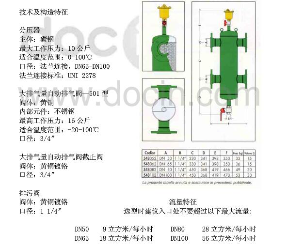
The basic part size of the hydraulic voltage divider
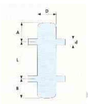
These are the size factors of the various parts of the voltage divider. Designing the voltage divider too low or too high can be detrimental to the system. For example, the diameter (D) of the voltage divider itself is relatively smaller than the interface diameter (d) (ie, the voltage divider is too slender). In this way, the pressure difference between the interfaces will rise very high and the significance of the voltage divider will actually be lost.
If the diameter of the voltage divider (D) is relatively larger than the interface diameter (d) (ie, the voltage divider is too large). This creates the danger of a two-way cycle: one cycle of water circulates on one side, and the other side of the water circulates in such a way that heat energy, such as that generated by a boiler or a condenser, is transferred to the end.

To design a hydraulic divider we compare the following methods:
1, three diameter method.
2, interface misalignment method.
3, the maximum flow method.
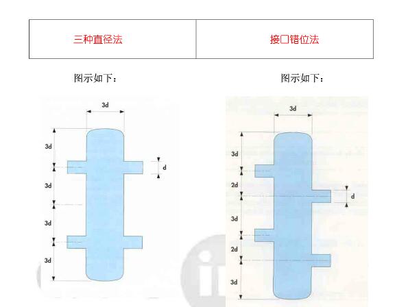
Three diameter methods and interface misalignment
Three diameters: Consider the flow rate (branches) less than 0.9 meters per second. If the above dimensional ratio is followed, it can be ensured that the differential pressure ΔP between the branch pipes is almost zero. At the same time to ensure the separation of water and gas and dirt deposition.
Interface misalignment method: The design generally considers the flow rate (branches) less than 1.2 m/s. This method has a higher flow rate than the three diameter methods, so that a small amount of turbulence is formed, reducing the risk of two-way circulation.
Maximum flow method
This method is suitable for prefabricated hydraulic pressure dividers.
This method is very simple, only need to consider the maximum flow through the voltage divider itself (one cycle and two cycles of flow): This data is provided by the manufacturer's technical samples.
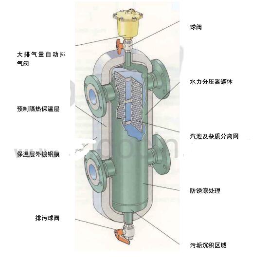
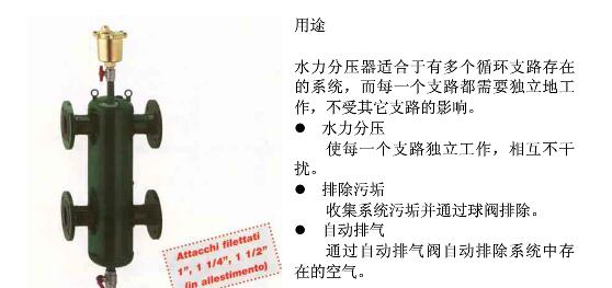
Some advantages of prefabricated hydraulic pressure divider applications
These prefabricated hydraulic pressure dividers are completely replacing hand-made hydraulic pressure dividers (which are manufactured by three diameter methods or interface misalignment) for the following reasons:
1. Its design is superior to hand-made design, it can provide the best appearance and size.
2. It has a design that is more suitable for automatic exhaust and dirt deposition than a hand-made voltage divider.
3. It has all undergone surface rust treatment, and the internal welding sites are also treated: this is very difficult to handle for hand-made.
4. It can be insulated and insulated (easy to install and replace).
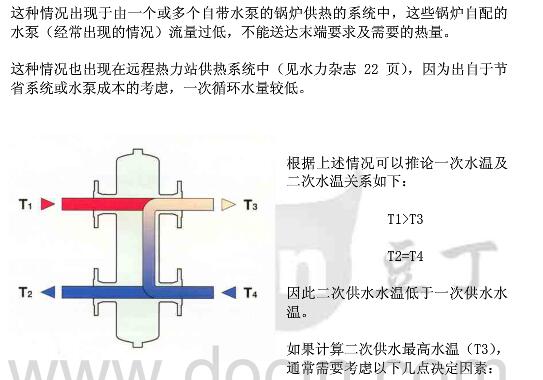
As we highlighted earlier: There is a clear water mixing inside the hydraulic pressure divider. For example, the 'hot' water supplied by the boiler (before reaching the end) may be cooled by the 'cold' water that is flowing back at the end. In this case, the design of the end should take into account this type of temperature drop, rather than based on the usual practice of basing the maximum water temperature on the boiler outlet.
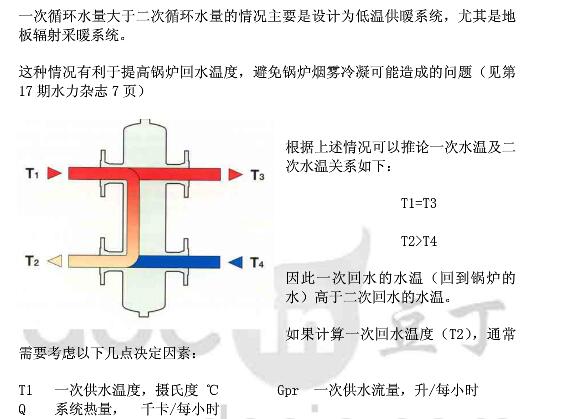
It is also possible that the 'cold' water flowing back at the end (before returning to the boiler) may be warmed by the 'hot' water supplied by the boiler. In this case (especially the floor heating system), the temperature rise of the boiler return water can be used to avoid boiler smoke condensation.
In the following, we begin to analyze the relationship between the temperature change caused by the voltage divider in the heating system (the principle in the refrigeration system is similar) and the change of primary and secondary water flow, which are roughly classified as follows:
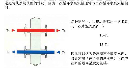
1, a circulating water volume is equal to the second circulating water volume.
2, a circulating water volume is less than the second circulating water volume.
3, a circulating water volume is greater than the second circulating water volume.
The amount of circulating water is equal to the amount of secondary circulating water
One cycle of water is less than the second cycle of water

The amount of circulating water is greater than the amount of secondary circulating water
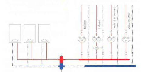
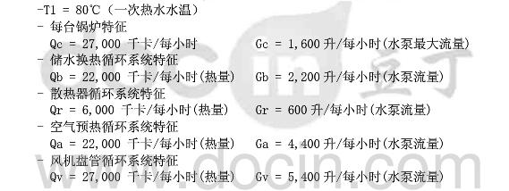
Calculate the system water temperature shown below. The system features are as follows:
calculation steps
First calculate the total required heat, one cycle of water flow and the second cycle of water flow. Then go to the following section: The amount of water in one cycle is less than the amount of water in the second cycle.
Total system heat
Add the heat of each circulation system: Q=Qb+Qr+Qa+Qv=77,000 kcal/hour
One cycle of water
Assume that the pressure loss of the circulatory system connected between the boiler and the water separator is small (for example, the horizontal pressure loss is: r = 5 mmHg/m3). According to the above assumption, the total circulating water volume is the sum of the maximum flow for all the boiler pumps. This gives: Gpr=3 X 1,600 = 4,800 L/h
Secondary water circulation
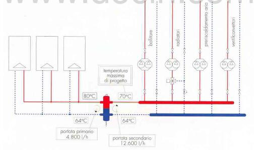
Calculate the flow rate of each circulating water in the secondary circulation: Gsec = Gb+Gr+Gv+Ga = 12,600 liters/hour Select the hydraulic pressure divider on the basis of the above flow rate (based on the amount of water above one cycle) .
Primary water and secondary water temperature difference
Use the formulas (1a) and (1b) to calculate:
△Tpr = Q/Gpr = 77,000/4,800 = 16°C
△Tsec = Q/Gsec = 77,000/12,600 = 6°C
One return water temperature
Calculate using formula (2): T2 = T1-△Tpr = 80-16 = 64°C
Secondary water supply temperature
Use formula (3) to calculate:
T3 = T4 + â–³Tsec = T2 + â–³sec
T3 = 64 + 6 = 70°C
This temperature is the basis for designing the highest water temperature required for coils, radiators, fan coils and air preheating units of storage water heaters.

Cummins ≥1000KW Diesel Generator
Cummins ≥1000Kw Diesel Generator,Cummins Open Diesel Generator,Canopy Type Diesel Generator,Cummins Power Generator Set
Shanghai Kosta Electric Co., Ltd. , https://www.ksdpower.com