Wireless monitoring has become an indispensable part of industrial production in safe production and timely collection of important data. Using modern information technology means to build a safety production supervision and management network system, we can do a good job in safety production and safety supervision and management. With the development of technology and the continuous expansion of mobile communication coverage, wireless monitoring systems based on GSM networks have been widely used in industrial control, power monitoring, intelligent buildings and data transmission, and GSM networks have low initial investment and no geographical restrictions. The high real-time communication advantages make it play a more important role in the field of wireless monitoring. The ARM9 processor utilizes high frequency, high speed, easy memory expansion, and can run the embedded Linux system design platform. Through the design of software and hardware modules, short message transmission is implemented on the GSM wireless network. This system can be applied to the monitoring of the environmental parameters of the oil recovery motor, and the parameters such as the pressure and temperature of the oil pipe can be monitored in real time to ensure the safe and normal operation of the oil well.
1 overall system designFigure 1 shows the short message monitoring system based on AT91RM9200. The platform mainly includes microprocessor unit, GSM/GPRS wireless module, storage module, serial communication module, network port communication module, USB module and power module.
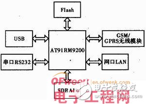
The embedded system platform built by the system is mainly used for processing, storing, sending and monitoring of collected data. The specific working principle is to transfer the downlink data to the flash memory through the serial port on the AT91RM9200 microprocessor with the main frequency of 180 MHz based on the ARM920T core, and then use the serial port, USB and 100 Mbit·s-1 Ethernet interfaces. The data is sent to the target, and data monitoring is performed by means of GSM wireless communication.
In the application process of the oil motor environment parameter transmission and communication system storage module, the system mainly stores the data after sampling and monitoring processing, and transmits it to the upper computer display through various interfaces, so that the staff can work on the underground motor environment. The data is observed and processed. The wireless transmission module can send the data received by the storage module to the well monitoring personnel in a wireless communication manner, so that the monitoring personnel can always know the oil production situation of the oil well.
2 system hardware circuit designThe short message receiving and transmitting function module of the system adopts Huawei's 4-band GSM/CPRS module MG323, and the working frequency band supports 4 frequencies: GSM850/900/1800/1900 MHz, receiving sensitivity "-107 dBm, working temperature -30 ~ +75 °C The power supply voltage is 3.3 to 4.8 V, and the average standby current is 3.0 mA. The protocol supports GSM/GPRS Phase 2/2+. MG232 contains a wealth of external application interfaces, including B2B connector interface, power interface, on/off and RESET timing, control signal interface, UART interface, SIM card interface, charging interface, audio interface.
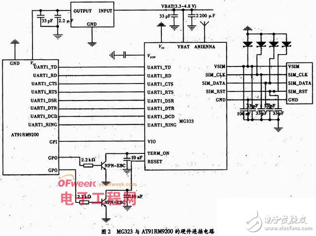
The hardware circuit of MG323 and AT91RM9200 is shown as in Fig. 2. ARM controls the switch of MG323 by controlling TERM_ON. When the TERM_ON pin is pulled low for ≥1 s, it can be turned on. After power-on, if the TERM_ON pin is pulled down for ≥1 s again, it can be turned off; control RESET to control MG323 Hardware reset, when the module crashes, the module performs hardware reset after pulling down the RESET pin for ≥10 ms.
Since the MG323 module provides an asynchronous RS-232UART1 communication interface and UART1 supports the standard Modem handshake control mode, the MG323GSM module is connected to the UART1 of the AT91RM 9200 through RS232. Its control signals are mainly: UART1_RD (module data transmitter), UART1_TD (module data receiver), UART1_RING (module ringer indication), UART1_ DSR (module data device ready), UART1_RTS (request to send), UART1_DTS (data terminal ready) ), UART1_CTS (module clear transmission), UART1_DCD (module carrier detection). The RT S/CTS sends a signal to the request, and the RTS is a ready signal to send the output. After the receiving parties are ready to send back the clear transmission signal CTS, the transmission data starts, and shorting the two signals at the same end means that the transmitter can be sent as long as the transmitter is ready. The DCD carrier detection is also called the receiving line signal detection. The intention is that after the Modem detects the carrier signal in the line, the signal that informs the terminal to prepare to receive the data can also be short-circuited with the RES and CTS if the modem is not connected. The DTR/DSR data terminal sends a DTR signal when it is ready, and can communicate after receiving the DSR signal from the data communication device. The original meaning of RING is valid when receiving a valid dialing of the telephone exchange, and the data terminal is ready to transmit.
The MG323 module is connected to the SIM card via signals SM_CLK (SIM card clock), VSIM (SIM card power), SIM_DATA (SIM card data), SIM_RST (SIM card reset), GND (SIM card ground).
The system also includes two 16 MB SDRAMs, two 8 MB NOR_Flash, three RS232, main USB, USB and 100 Mbit·s-1 Ethernet modules.
3 system software designThe design of the system software is mainly based on the programming of C under Linux. The wireless monitoring program controls the GSM module according to the principle of short message transmission and reception.
3.1 Principle of short message transmission and reception
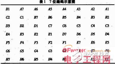
The maximum length of short message content is 140 Bytes. Its encoding mainly has 7-bit encoding, 8-bit encoding, and UC2 encoding 3 encoding methods. The 7-bit code uses only the lower 7 bits per Byte, and each 8 By te is a group, the highest bit is removed, and the code is re-encoded to 7 Bytes. Therefore, the 7-bit code can actually represent 160 Bytes. However, the 7-bit code can only send characters ranging from 0x00 to 0x7F, which is generally used when sending English text messages. The coding principle is: every 8 Bytes is a group, respectively, A, B, C, D, E, F, G for 8 Byte, An for each Byte bit, then 8 Byte re-encoded as shown in Table 1. 7 Byte.
The 8-bit encoding is a WYSIWYG encoding method, that is, no encoding is required, as long as the binary string is directly transmitted. The 8-bit encoding method is suitable for developing various short message-based communication protocols. U C2 encoding is often used for Chinese or Chinese and English mixed content transmission, and can only send 70 characters (1 UC2 occupies 2 Bytes). Since most domestic editors are GB coded, if you want to send Chinese, you need to convert Chinese to UC2 ​​code and then send it. On mobile phones, the usual practice is to send them in 7-bit code if all are in English and half-width characters. If Chinese is included, all codes are sent as UC2.
The short message transmission mode is mainly divided into a text mode and a PDU mode. The text mode is actually a package for 7-bit encoding. It can only be used to send ANSI-wide characters, and the sending method is simple. All short message data in the PDU mode must be organized into a PDU format. Sending a short message in the PDU mode is complicated. You need to organize the PDU content yourself, but the sending method is flexible, you can send various data, or you can set each one. The content of the PDU field.
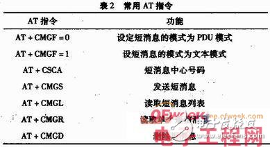
3.2 commonly used short message AT command
The GSM wireless module communicates using a standard AT command set, which is used to control the mutual rules between TE (Terminal Equipment) (such as PC and other user terminals) and MT (Mobile Terminal) (such as mobile terminals such as mobile stations). AT command types are mainly divided into basic commands, S register commands, extensions, and vendor-defined commands.
3.3 Implementation of the GSM program
ARM and GSM communication is based on the serial port corresponding to ttyS1, and is connected with a UART interface provided by MG323, supporting short message, phone book management, data service, embedded TCP/UDP and other functions. Using ARM to issue the AT command set to perform corresponding operations on the GSM module, the function of sending short messages can be completed. The specific software flow is shown in Figure 3.
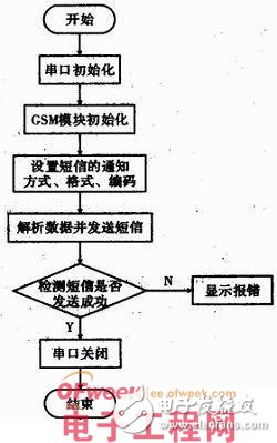
The initialization of the serial port is mainly the baud rate, parity bit and stop bit settings. After configuring the relevant attributes of the serial port, you can drill and read and write the serial port. On a Linux system, all device files are located under "/dev". The device corresponding to serial port 2 is named "/dev/ttyS1". The operation method of the device and the file is the same under Linux, so the serial port is the same. Reading and writing can be done using simple "read" and "write" functions.
The initialization of the GSM module is mainly to send "AT" to the MT (Mobil Terminal) to see if there is a reply to determine that the ARM and GSM serial ports are working properly. After confirming that the serial port is working normally, send the “ATE0†command to turn off the echo of the MT.
Set the SMS notification method, SMS format (PDU), and SMS encoding (USC2). If the setting of each function is normal, the short message of "GSM module initialization successful" is sent to the specified user according to the PDV format.
Parsing the data and sending the text message is mainly to fill the first 46 Bytes of the buffer that sent the MT in the PDU format. Then open the data storage file and use the lseek function to move the file cursor forward by 17 bytes from the end of the file. Since the data in the data frame is represented by a hexadecimal 2 Byte, it is first combined into a 16-bit short integer, and then the combined data is added to the check digit. After processing the data, the last message is sent and the MT reply is checked for the +CMGS command. If there is, the message is sent successfully.
4 ConclusionThe embedded Linux system is built with the AT91RM9200 processor, and the short message is transmitted by using the GSM/GPRS wireless communication module. At the same time, the embedded system plus GSM module system is compact and stable, suitable for remote areas or mobile data acquisition systems, providing a new means of data acquisition and monitoring. As wireless communication systems continue to evolve and mature, it will penetrate into every aspect of life.
Others Patent Vape,Air Bars Disposable,Disposable Vapor Pen,Disposable E-Cigarette
Guangzhou Yunge Tianhong Electronic Technology Co., Ltd , https://www.e-cigaretteyfactory.com