The introduced electronic transformer overcomes the disadvantages of traditional silicon steel transformers such as large size, heavy weight, low efficiency, and high price. The circuit is mature and its performance is stable.
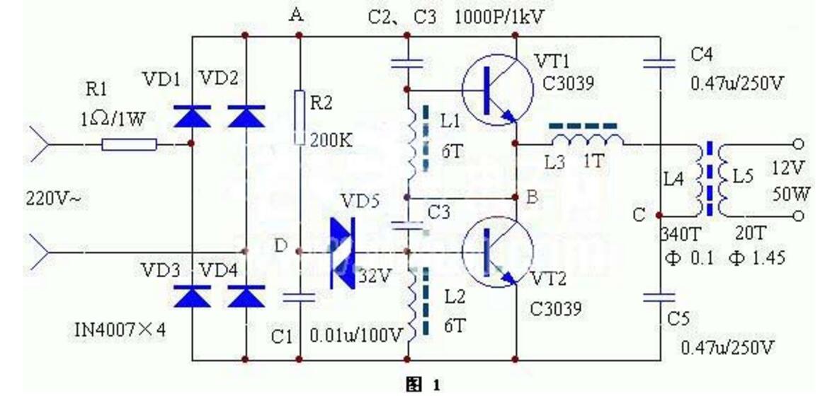
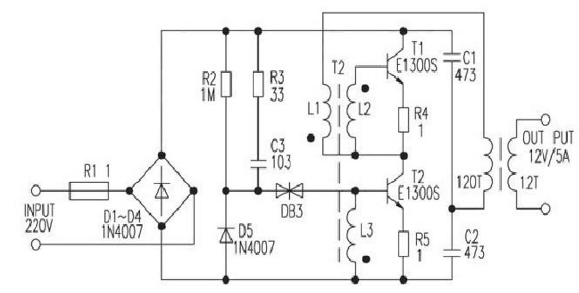
The working principle of the electronic transformer is similar to that of the switching power supply. The circuit schematic is shown in Fig. 1. The mains is rectified to DC by VD1-VD4, then the DC is changed to high-frequency current of several tens of kHz, and then the ferrite breaker is used to increase the Frequency, high pressure pulse buck. In the figure, R2, C1, and VD5 are start trigger circuits. C2, C3, L1, L2, L3, VT1, and VT2 constitute a high frequency oscillation section.
Component selection and production
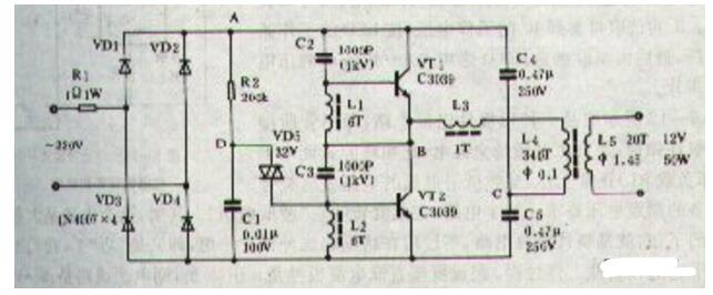
L1, L2, and L3 were wound on magnetic cores of H7&Times; 4&Times; 2mm3, L1 and L2 were wound 6 turns, and L2 was wound 1 turn. L4 and L5 are wound on a magnetic ring of H31&Times;18&Times; 7mm3. L4 is wound around 340 turns of a high-strength wire with Φ=0.1mm; L5 is wound with 20 turns of a high-intensity wire of Φ=1.45mm. VT1, VT2 use pressure BVceo ≥ 350V high power silicon tube. There are no special requirements for other components.
When the circuit works normally, the voltage at point A is about 215V, point B is about 108V, point C is about 10V, and point D is about 25V. If it does not oscillate, check whether the phases of VT1, VT2, and L1, L2, and L3 are normal (exchange the two wires of L3 immediately). Changing the number of turns of L5 can change the output voltage.
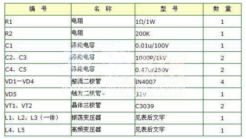
500W high power transformer circuitThe picture shows the 500W high power transformer circuit principle. The circuit uses TL494 as the oscillator and VT1 to VT6 as the excitation stage. It is a high-power inverter circuit with an output of 500W. The application method of TL494 in this inverter is as follows: 1. Pin 2 constitutes a constant voltage sampling and error amplifying circuit f The 15V DC voltage of the secondary winding rectified output of the inverter is used as the sampling voltage, and is divided by R1 and R3 to make 1 The foot has a sampling voltage of approximately 4.7 to 5.6 V during normal operation of the inverter. 2 feet input 5V reference voltage (output by 14 feet). When the output voltage decreases, the voltage of pin 1 decreases and the error amplifier outputs a low level, and the output voltage rises through the internal circuit of the TL494.
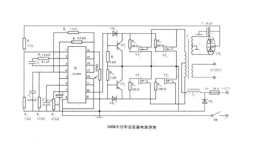
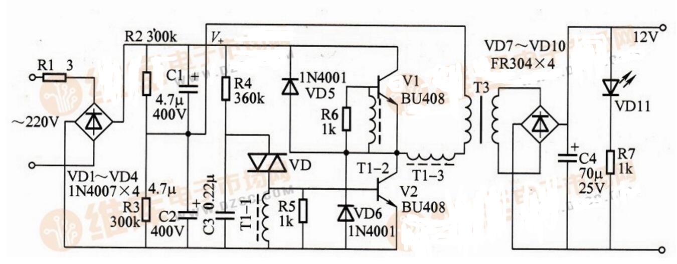
After repeated experiments, the electronic transformer's current response speed is very fast! Has exceeded the common power frequency transformer, this circuit can completely replace the power amplifier. The electronic transformer AC/DC has an over-current limit protection function suitable for battery charging of electric bicycles. If several AC/DCs are connected in parallel, they can be made into high-powered chargers. Because this circuit's ability to adapt to current changes is very strong, it can be used in parallel to replace a few KW's fire cows.
Self-excited electronic transformer circuit diagram
The working principle of the electronic transformer is similar to that of a switching power supply. The mains is converted into DC by VD1 to VD4, and then the DC is converted into a high-frequency current of several tens of kilohertz, and then the ferrite transformer is used to step down the high-frequency and high-voltage pulses ( as the picture shows). In the figure, R2, C1, and VD5 are start trigger circuits. C2, C3, L1, L2, L3, VT1, and VT2 constitute a high frequency oscillation section.
Telecom systems is the exchange of information over significant distances by electronic means. A complete, single telecommunications circuit consists of two stations, each equipped with a transmitter and a receiver. And we will offer the basic telecom products which you may familiar in your life to build up the telecom systems.
From Data center with a floor standing cabinets, you may get your sign out .For distribution outdoor, you may need a waterproof Distribution Box to exchange the singals. Meanwhile, you may have a terminal block with 10 pair disconnection Krone Module and lighting protectors(LSA single pair type or STB module). When you distribute in house, there are more products in application like voice patch panels, keystone jacks, face plate, 3M connectors(like UY connectors), AMP picapond connector, wall outlets, surface mount box, and so on. Sure there is a must to get the right tool to finish operations, kinds of tools for selection: Insertion tools, punch tool, crimping tool, wire cutter, cable stripper. Hot sale for krone insertion tool, RJ45 crimping tools, Ericsson punch down tool, AMP picabond ratechet crimper, Coaxial cable crimping tool .
We insist on compact size to ensure an easy but smart and reliable installation in every product of the telecom systems we offer. That is the final aim we work on solution, to make it perfect we also provide OEM service to satisfy your special demand. Till now, we have successfully take part in many Telecom projects in Russia, Sri Lanka, Greece, Ecuador, ect.. We have full experience in such tenders for building up telecom systems.
We keep on working just like the Cable Ring Managers to keep everything Orderly, Fast and Effective. Believe us and we will help you to be the winner !

Outdoor Distribution Box, LSA Krone Module, Mounting Frame, STB Module, Picabond Connector , Crimping Tool
NINGBO YULIANG TELECOM MUNICATIONS EQUIPMENT CO.,LTD. , https://www.yltelecom.com