The volumetric flowmeter has the advantages of stable function, high accuracy, wide range and large measurement range, so it is widely used in industrial flow measurement.
The rotary piston flowmeter is a volumetric flowmeter, and the problem of the isolation and sealing of the inlet and outlet chambers of the measurement chamber is an important link related to whether it can ensure accurate and stable measurement. The seal is formed by the contact of the rotating piston with the inner and outer cylinders and the partition plate, and the top notch profile design that is in contact with the partition plate for the piston to swing is particularly critical. When working, the profile must ensure that the piston is pressed correctly. The trajectory movement is not subject to interference, and the gap profile must be kept in contact with the partition to isolate the entrance and exit chambers and form a reliable seal.
Structure and working principle of measuring chamber of rotary piston flowmeter

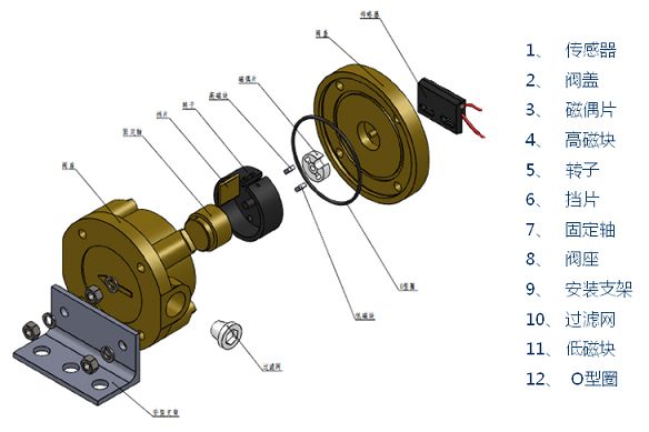
As shown in FIG. 1, the piston 7 with a gap on the top surface capable of accommodating the position gap of the partition plate is located in the annular area formed by the inner wall of the outer cylinder 1 and the outer wall of the inner cylinder 6, the inner and outer walls of the piston and the inner and outer cylinders are respectively The outer and inner walls of the piston make the center o'of the piston have an offset distance e from the center o of the inner and outer cylinders. It is not difficult to see that the outer and inner radii of the rotating piston r 1, r 2, and the inner and outer radii of the outer and inner cylinders R, r 3 Has the following relationship:
Piston wall thickness δ= r 1- r 2 Offset distance e= R-r 1 Piston outer radius r 1= (R + r 3+ δ) / 2 There is a radial partition between the inner and outer cylinders to divide the annular area.
The radial dimension of the annular zone I = R-r 3 The length of the separator within R l 1 is slightly larger than the thickness of the separator b is the distance from the separator to the point o 2 l = R-l 1
In this way, the annular area is divided into two crescent-shaped inner and outer cavity measuring chambers by the piston wall and the partition. Under the action of the inlet liquid pressure, the piston center o'rotates counterclockwise around the arrow along the arrow, and the rest of the piston swings in the annular area The inner and outer cylindrical surfaces come into contact with the inner and outer cylinders in sequence, and the metering chamber continuously moves in a circle to transport fluid. The center o'of the piston makes one revolution around o, and the inner and outer metering chambers also make one revolution at the same time. The volume of the crescent-shaped internal and external metering cavity and the volume flow of the liquid discharged and discharged in one revolution of the center of the piston, which is a measurable constant:

Among them, h—the height of the measuring room
According to the revolution n of the piston, the amount of liquid flowing under the revolution n can be measured:

Analysis of the sealing problem of the flowmeter measuring room
1. Sealing principle
From the above analysis of the flowmeter structure and working principle, it can be seen that when the piston is working, the outer circular surface of the piston, the inner circular surface of the outer cylinder and their mutual contact, the partition and the upper and lower surfaces of the cylinder form the outer measuring chamber; and the inner circular surface of the piston, The outer circular surface of the inner cylinder and their mutual contact, the partition and the upper and lower surfaces of the cylinder constitute the inner measuring chamber. When the piston moves, it requires a gap between the top surface and the diaphragm to ensure that the movement is not interfered. More importantly, the gap profile must also ensure that it always contacts the k point near the center of the diaphragm to ensure internal measurement. The sealing of the chamber; otherwise, the liquid input from the inlet with pressure will not be transported through the metering chamber, but will directly flow into the outlet through the gap and flow out, ranging from inaccurate measurement to heavy, the flowmeter will not work.
2. Analysis and design calculation of the profile equation of the top surface of the piston
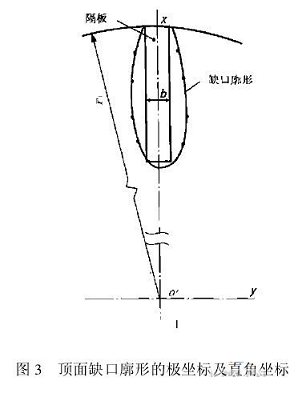
1) As shown in Fig. 2, the center of the rotary piston rotates counterclockwise o'around o, and the angle between the line oo' and the initial position is set to α. Using α as a parameter, the polar coordinate parameter equation of the top notch profile is derived . For the convenience of design and processing, the polar coordinate system is fixed on the top surface of the piston. Let the origin of the coordinate system be o', the initial position of the polar axis is the symmetry line o'B of the notch profile, and the clockwise direction is the positive phase angle φ.
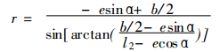
When 0° ≤ α ≤ 180°, the right half profile equation of the notch is derived as:


Among them, e, b, l 2 and r 1 are all known as mentioned above.

2) When 180°≤α≤360°, due to the symmetrical relationship, -α, -φ is substituted for α in (1), φ can obtain the polar coordinate equation when 180°≤α≤360°:

3. Instance calculation
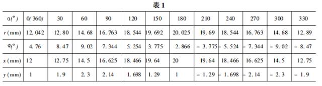
Original data: R = 27 mm, r 1 = 23 mm, r 2 = 21 mm, r 3 = 17 mm, l 1 = 11 mm, b = 2 mm
After calculation, e = R-r 1 = 4 mm, l 3 = 16 mm, the parameter α takes values ​​from small to large, and the corresponding values ​​of r and φ are shown in Table 1.
Profile processing
Convert equations (1) and (2) into a rectangular coordinate equation, as shown in Figure 3:
(3) The formula is still the parametric equation of α. It is difficult to directly obtain the functional relationship y = f (x) of y and x. You can obtain the corresponding values ​​of x and y according to the given value of α (see the table above). The corresponding coordinate point is used as a node, and the piecewise y = f (x) equation is established by Newton's difference interpolation or spline interpolation; on the basis of this equation, a program can be compiled to facilitate the processing on the NCN wire cutting machine.
Other measures to improve seal reliability
1) The leakage of liquid at the gap on the top surface of the piston mainly occurs in the inner metering chamber. Try to shorten the communication time between the inner metering chamber and the inlet, so as to reduce the time course of the pressure effect. When designing the shape and position of the inlet, make the inlet as close as possible to the outside The inner cylindrical surface of the cylinder.
2) Similarly, the shape and position of the liquid outlet should be communicated with the metering cavity as soon as possible.
in conclusion
1. The dynamic seal of the measuring chamber of the rotary piston flowmeter should carefully consider the size relationship between the radius of the cylinder and the eccentricity of the radius of the piston, so that the inner and outer cylindrical surfaces of the piston are in contact with the inner and outer cylindrical surfaces of the cylinder. Consider the contact seal of the top surface of the piston and the diaphragm, that is, the outline design of the gap.
2. The notch profile design of the top surface of the piston must meet its own normal movement without interference, but also consider the problem of dynamic sealing there. Therefore, the shape of the notch is not random, but is carefully designed as shown in Figure 3.
3. The notch profile of the top surface of the piston can be designed and calculated according to the formulas (1) and (2).
4. The profile can be obtained through the (1), (2), (3) parameter equations to obtain the node fitting interpolation equation, and the processing is completed on the CNC wire cutting machine.
U-How® Confluence Fuel Flowmeter
U-How® Conway Flowmeter is independently developed and produced by Shanghai Conway Industrial Development Co., Ltd. based on the rotary piston working principle. It has the characteristics of low flow rate, wide range, high accuracy, simple structure, safe and reliable operation, etc. Flow Sensors.
Product Image
working principle
The rotary piston flowmeter is a volumetric flowmeter, which is based on the tangential sealing state that the piston and the measuring chamber have always maintained. There is also a fixed eccentricity measuring element piston. Under the action of the pressure difference, the piston generates a rotational torque to make the piston make an eccentric rotary motion. The rotation speed of the piston is proportional to the flow rate of the fluid. The rotation speed of the piston is recorded by the counting mechanism , You can measure the total fluid flow.
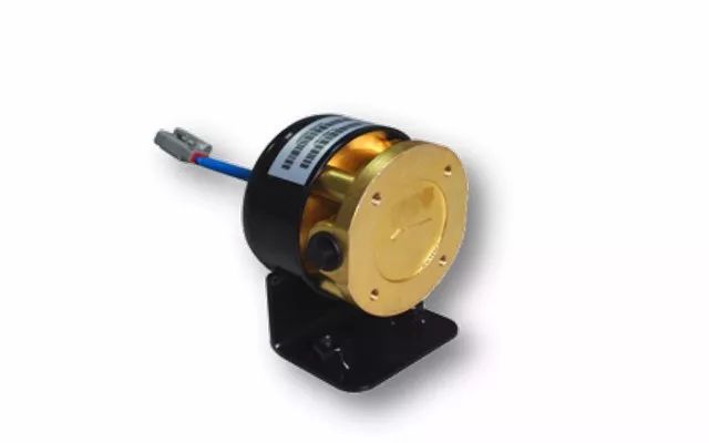
The inlet and outlet of the rotary piston flowmeter are separated by a partition. When the measured fluid enters the metering chamber from the inlet, a pressure difference is formed at the inlet and outlet, forcing the piston to rotate counterclockwise as shown in Figure a. The fluid flows in continuously, forcing the piston to rotate as shown in Figure b, forming two half-moon crescent cavities, forcing the piston to rotate under the effect of the pressure difference as shown in Figure c, V2 fluid is discharged from the outlet, and the piston rotates as shown in Figure d. Rotating under the effect of difference, the fluid burst out every revolution of the piston is equal to the sum of V1+V2.
Working principle diagram
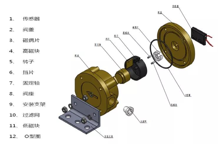
Flowmeter explosion diagram:
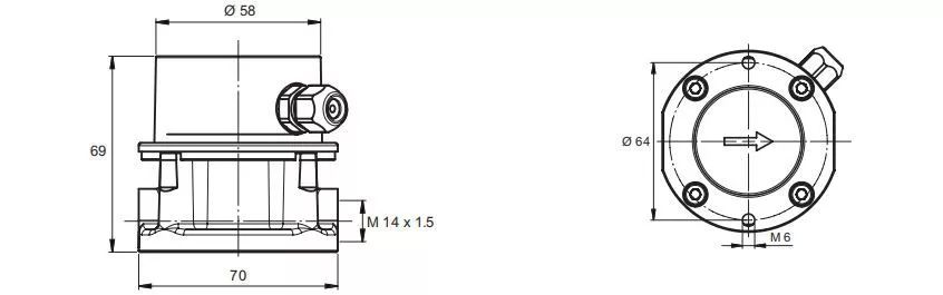
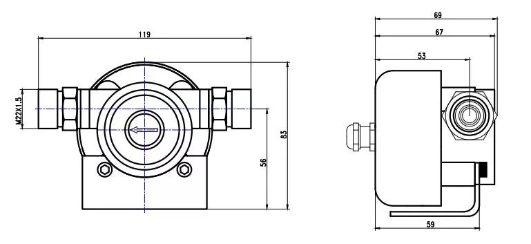
Structure size drawing:
PDFM4D

PDFM8D
PDFM8DB
Product parameters
1. Mechanical part:
| model | PDFM 4D | PDFM 8D | PDFM 8Db |
| Hydraulic connector | M14 x1.5 | M14 x1.5 | M16/22 x1.5 |
| Working pressure (MPa) | 2.5 | 2.5 | 2.5 |
| Measuring range (l/h) | 1~ 80 | 20~ 200 | 80~ 320 |
| Accuracy (﹪) | ±1 | ±1 | ±1 |
| Repetition rate (﹪) | ±0.2 | ±0.2 | ±0.2 |
| Measuring chamber volume (Ml) | 5 | 12.44 | 12.44 |
| Built-in filter size (mm) | 0.125 | 0.15 | 0.15 |
| Working temperature (℃) | ﹣20 ~80 | ﹣20 ~80 | ﹣20 ~80 |
| Storage temperature (℃) | ﹣40 ~100 | ﹣40 ~100 | ﹣40 ~100 |
2. Electronic part:
| Model size | KHDQ |
| Working voltage (V) | 9~40 |
| Output Interface | RS485/RS232 |
| Data cable | 2×0.75 |
| Working temperature (℃) | ﹣20~80 |
| Storage temperature (℃) | ﹣40~100 |
Measuring medium:
Can measure light and medium oil, such as: gasoline, diesel, kerosene, naphtha, lubricating oil
Product Qualification
1. Invention patent: ZL201020504169.8 flow sensor
2. Vehicle inspection report of National Automobile Quality Supervision and Inspection Center
3. The Ministry of Communications entrusted the Beijing Metrology Institute to test the accuracy
Fuel consumption monitoring solution
Application object
1. Engine:
Measure the fuel consumption of various power machines in trains, automobiles, engineering vehicles, tractors, generator sets and ships sailing in inland or offshore waters, as well as the loading and unloading measurement of various heavier liquids and the measurement of pipeline over-liquidation.
2. Burner:
Fuel consumption measurement of on-board boilers, mobile boilers and other equipment.
Data collection method
By collecting the pulse data of the flowmeter, the system integration of the equipment unit is connected by RS485/RS232
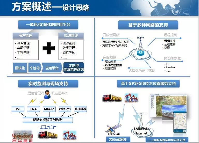
solution

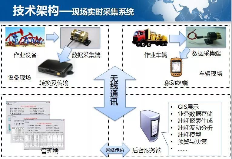
Implementation case
A large oil group:
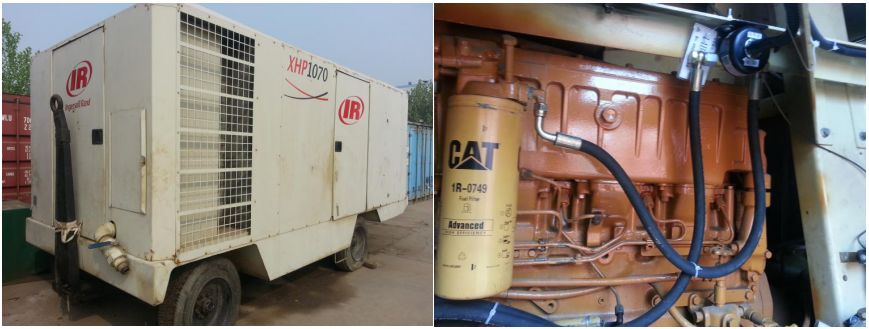
Pipelayer, mobile power station, multi-function vehicle, pipe bender, air compressor, etc.
A large oil production plant:
Boiler truck, wax cleaning truck, superconducting truck, cement truck, crane, etc.;
port:
Gantry crane, stacker, front crane, loader, etc.
other:
Tire pressure and fuel consumption test; driver driving skills competition; engine performance calibration
Air compressor
Boiler car

Promotion Power Station for EU
Promotion Power Station For Eu,Portable Power Station,Solar Power Station,Power Station For Laptop
Guangzhou Fengjiu New Energy Technology Co.,Ltd , http://www.flashfishbatteries.com