1602 liquid crystal is also called 1602 character type liquid crystal, which is a dot matrix type liquid crystal module specially used for displaying letters, numbers, symbols and the like. It consists of several 5X7 or 5X11 dot matrix characters. Each dot character can display one character. There is a dot interval between each bit. There is also a gap between each line, which plays the character spacing and line. The effect of the spacing, because of this, it does not display graphics well (using custom CGRAM, the display is not good).
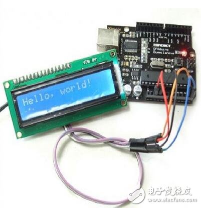
LCD1602 means that the displayed content is 16X2, that is, two lines of 16-character liquid crystal modules (display characters and numbers) can be displayed.
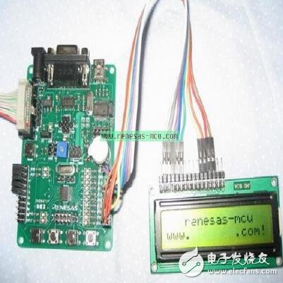
Most of the character LCDs on the market are based on the HD44780 liquid crystal chip, and the control principle is completely the same. Therefore, the control program written based on HD44780 can be conveniently applied to most character liquid crystals on the market.
LCD1602 - Features+5V voltage, adjustable contrast
Built-in reset circuit
Provide various control commands, such as: clear screen, character flashing, cursor blinking, display shift, etc.
80 bytes display data memory DDRAM
Built-in 192 5X7 dot matrix character generator CGROM
8 user-definable 5X7 character generators CGRAM
1602LCD uses standard 14-pin (no backlight) or 16-pin (with backlight) interface
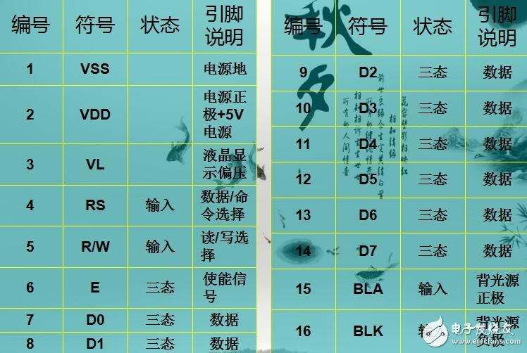
LCD1602 - Pin Function Introduction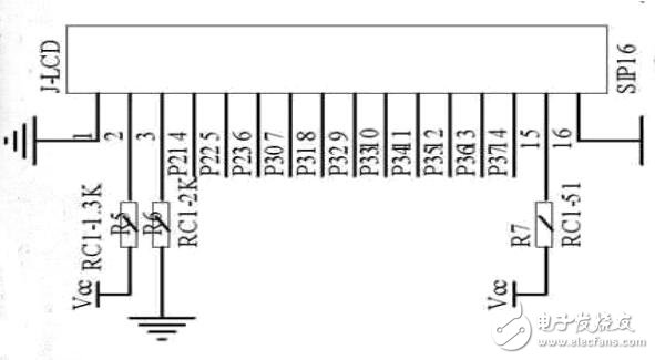
Pin 1: VSS is the power ground
Pin 2: VDD is connected to the 5V power supply positive
Pin 3: V0 is the contrast adjustment end of the LCD. When the positive power is connected, the contrast is the weakest. When the grounding power is used, the contrast is the highest (the ghost is generated when the contrast is too high, and the contrast can be adjusted by a 10K potentiometer when using it).
Pin 4: RS is the register selection. When the high level is 1, the data register is selected, and when the low level is 0, the instruction register is selected.
Pin 5: RW is a read/write signal line. When a high level (1) is read, a low level (0) is written.
Pin 6: The E (or EN) end is the enable end.
Pins 7 to 14: D0 to D7 are 8-bit bidirectional data terminals.
Foot 15~16: Empty foot or backlight power supply. 15 feet of backlight positive, 16 feet of backlight negative.
Command 1: Clear display, command code 01H, cursor reset to address 00H position.
Instruction 2: The cursor is reset and the cursor returns to address 00H.
Instruction 3: Cursor and display mode setting I/D: cursor movement direction, high level right shift, low level left shift S: Whether all characters on the screen move left or right. A high level indicates a valid level and a low level indicates an invalid state.
Instruction 4: Display switch control. D: Controls the overall display on and off, high level means open display, low level means off display C: control cursor on and off, high level means there is cursor, low level means no cursor B: control cursor Blinking, high level flashing, low level does not flash.
Command 5: Cursor or display shift S/C: Moves the displayed text when it is high, and moves the cursor when it is low.
Command 6: Function setting command DL: 4-bit bus when high level, 8-bit bus when low level: Single line display when low level, double line display when high level: Display 5x7 dot matrix character when low level, A 5x10 dot matrix character is displayed at a high level.
Instruction 7: Character generator RAM address setting.
Instruction 8: DDRAM address setting.
Instruction 9: Read busy signal and cursor address BF: Busy flag, high level means busy, the module can't receive command or data at this time, if it is low, it means not busy.
Instruction 10: Write data.
Instruction 11: Read data.
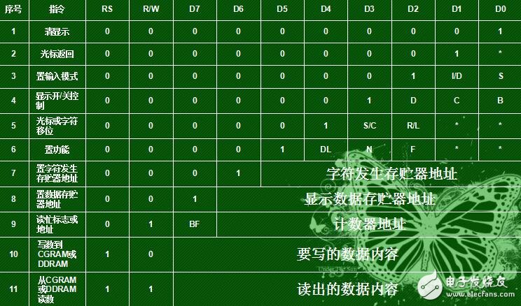
Control command table
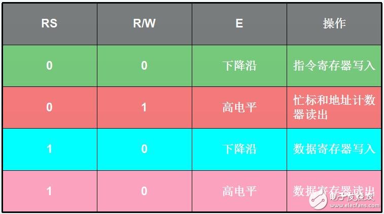
LCD pin control
LCD1602 - RegisterMost of the 1602 is based on the HD44780 liquid crystal chip. The HD44780 has built-in DDRAM, CGROM and CGRAM, all of which are memory.
CGROM (Chinese character library), HCGROM (ASCII code font) and CGRAM (custom font), display data RAM (DDRAM), character display RAM buffer (DDRAM)
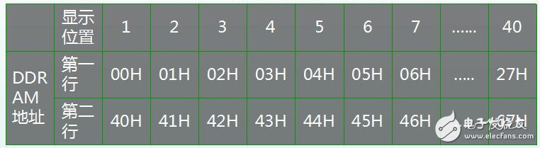
But one line has 40 addresses, we only use the first 16 addresses, the second line also uses the first 16 addresses, the corresponding address is as follows
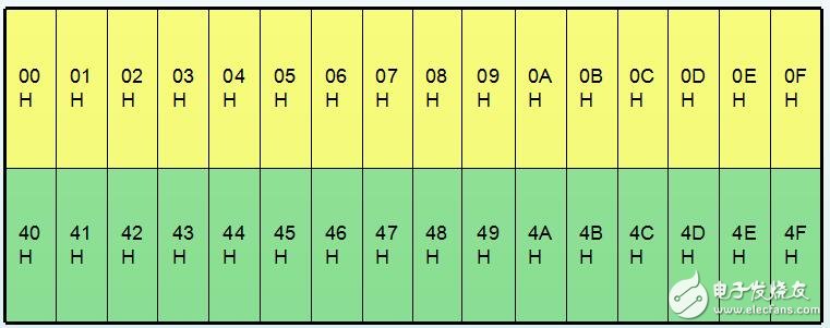
DDRAM (display data storage RAM)
If you want to display the "A" character in the first column of the first line of the screen, it is necessary to write the code "A" in the 00H address of the DDRAM.
When we send data to the 00H address in DDRAM, such as the code of the number 1, but it does not show 1 out. This is the most error-prone place for us. If you want to display data to 00H, you must add 00H to 80H, which is 0X80H+0X00H. If it is at 01H, it is 0X80H+0X01H, and so on.
LCD1602—CGROM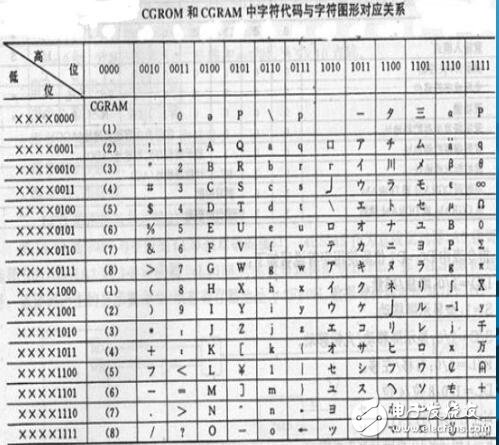
The character generation memory (CGROM) inside the 1602 liquid crystal module has stored 160 different dot matrix character patterns. These characters are: Arabic numerals, uppercase and lowercase letters of English letters, commonly used symbols, and Japanese kana, each with a fixed code.
It can be seen from the above table that the leftmost column is for user-defined characters. There are 16 in total, and only 8 bytes can be used. The character code is 8000000-00000111.
LCD1602—Display Application (SCM Learning)LCD1602 is one of the most important modules in 51 single-chip microcomputer. In order to facilitate the novice to learn 1602, the author has taken some experience of learning 1602 and shared it with the rookie. Because the author's level is limited, the error is inevitable. I hope everyone corrects. This program is based on the Huijing HJ-1G51 development board. Many programs are written by themselves and can be used directly.
First, about LCD1602:
Before writing the LCD1602 program, we must understand some very important information in the manual. If the information is not understood, the programming may encounter more or less problems. Here are a few general points.
1. Pin:
1602 has a total of 16 pins, but the main pins used for programming are only three, namely: RS (data command selection), R/W (read and write selection), E (enable signal); Mainly around these three pins to expand to initialize, write commands, write data.
The three pins are specifically described below:
RS is the register selection, the high level selects the data register, and the low level selects the instruction register.
R/W is for read/write selection, high level for read operation and low level for write operation.
The E terminal is the enable terminal, and the latter is associated with the timing.
In addition, D0~D7 are 8-bit bidirectional data lines respectively.
2. Operation timing:
RS
R/W
Instructions
0
0
Write instruction code D0~D7
0
1
Read the output D0~D7 status word
1
0
Write data D0~D7
1
1
Read data from D0~D7
Note: About E=H pulse - Initialize E to 0 at the beginning, then set E to 1, then clear 0.
When reading the status word, pay attention to the D7 bit, D7=1, prohibit reading and writing operations; D7=0, allow read and write operations;
Therefore, read and write detection must be performed before the controller performs read and write operations. (ie the latter read busy subroutine)
3. Instruction Set:
LCD_1602 initialization command summary:
0x38
Set 16*2 display, 5*7 dot matrix, 8-bit data interface
0x01
Clear screen
0x0F
On display, display cursor, cursor blinks
0x08
Only open display
0x0e
Open display, display cursor, cursor does not flash
0x0c
On display, no cursor is displayed
0x06
Add 1 to the address, move the cursor to the right when writing data
0x02
Address counter AC=0; (at this time the address is 0x80)
The cursor is at the origin, but the DDRAM interrupt remains unchanged.
0x18
Cursor and display move to the left
4. Display address:
The LCD1602 internal RAM displays the map of the buffer address. 00~0F and 40~4F respectively correspond to each character of the upper and lower lines of the LCD1602. As long as the ASCII code of the character to be displayed is written to the corresponding RAM address, it can be displayed.
5. Read and write timing:
The timing diagram 1602 is in the manual and is not quoted here. The timing diagram is very important. Programming is to set the register according to the timing diagram to make the LCD work.
Second, LCD1602 program writing process:
LCD1602 can be written after understanding the above information, here we divide the program into the following steps:
1. Define the LCD1602 pins, including RS, R/W, and E. The definition here means that these pins are connected to which I/O ports of the microcontroller.
Here are some examples:
Sbit EN=P3^4;
Sbit RS=P3^5;
Sbit RW=P3^6;
2. Display initialization, initialization and setting display mode in this step, including the following steps:
Set display mode
Delay
Clean up the display cache
Set display mode
The recommended initialization process is as follows:
Delay 15ms
Write instruction 38H
Delay 5ms
Write instruction 38H
Delay 5ms
Write instruction 38H
Delay 5ms
Note: The above 38H instruction can be read to omit 1~2 steps.
(The above does not detect the busy signal)
(The following must detect the busy signal)
Write instruction 38H
Write command 08H to close the display
Write command 01H to display clear screen
Write command 06H cursor movement setting
Write command 0cH display on and cursor settings
3. Set the display address (write the position where the character is displayed).
4. Write data showing characters.
Third, LCD1602 subroutine modules and main program preparation:
Now, according to the flow of the above program, the examples of each subroutine module and main program are given.
1. Header files, macro definitions, definition pins, etc.:
#include"reg52.h"
#include 《string.h》
#define uchar unsigned char
#define uint unsigned int
Sbit EN=P3^4;
Sbit RS=P3^5;
Sbit RW=P3^6;
Uchar code table0[]={"QQ"
};
/ / This statement is an array of strings defined when the string is displayed
2. LCD1602 basic initialization subroutine:
Void LCD1602()
{
EN=0;
RS=1;
RW=1;
P0=0xff;
//P0 here is the I/O port connected to LCD D0~D7
}
3. Read the busy subroutine:
Void read_busy()
{
P0=0xff;
RS=0;
RW=1;
EN=1;
While(P0&0x80);
//P0 and 10000000 are matched, if the D7 bit is not 0, stop here.
EN=0;
/ / If 0 jumped out to the next step; the role of this statement is to detect
}
/ / D7 bit, if busy waiting here, not busy jumping out of the read busy subroutine to execute read and write instructions
4. Write instruction to write data subroutine:
Void write(uchar i,bit j)
{
Read_busy();
P0=i;
//where i=0, write instruction; i=1, write data;
RS=j;
RW=0;
EN=1;
EN=0;
}
5. Delay subroutine:
Void delay(uint c)
/ / Function is to provide delay in other subroutines such as initialization 1xc MS
{
Uint a,b;
For(a=0;a"c;a++)
For(b=0;b"120;b++);
}
6. LCD1602 initialization subroutine:
Void init()
/ / Complete the process according to the requirements, the first step in the middle of the write instruction 38H
{
Delay(15);
Write(0x38,0);
Delay(5);
Write(0x38,0);
Write(0x08,0);
Write(0x01,0);
Write(0x06,0);
Write(0x0c,0);
}
7. Display a single character subroutine:
Void display_lcd_byte(uchar y,uchar x,uchar z)
//Y=0,1 (starting line),
{
// X=0~15 (start column), Z=ASCII code to write characters
If(y)
/ / Is it displayed in the second line (if Y=0 in the first line, do not enter the IF statement, if in the first
{
/ / Two lines, enter the IF statement
x+=0x40;
/ / The second line starting address plus the number of columns for the character display address
}
x+=0x80;
/ / Set the data pointer position
Write(x,0);
Write(z,1);
//data input
}
8. Display string subroutine:
Void display_lcd_text(uchar y, uchar x, uchar table[])
{
//Y (starting line), X (starting column) with the same character display, table[] string array
Uchar z=0;
Uchar t;
t=strlen(table)+x;
//
Find the length of the string plus the starting column position
While(x"t)
/ / Function for the LCD to display the last character of the string, to prevent strings
{
/ / There are no 16 characters, so the boring is not enough bits;
Display_lcd_byte(y,x,table[z]);
/ / Display the characters in the array bit by bit
x++;
z++;
}
}
9. Main program:
In addition to the initialization program, the main program is to add the display subroutine that you have written. You can write various types of display subroutines according to the functions you need. This is not described in detail here. The following example shows a character and display string. Display subroutine.
Void main()
{
LCD1602();
Init();
Display_lcd_byte(0,0,'A');
//
Display a character
Display_lcd_text(1,3,table);
//
Display string
While(1);
}
At this point, the operation flow and programming ideas of the LCD1602 display can basically come to an end, but the function realization of the 1602 is much more than that. With 1602 you can display dynamic effects, and in addition to displaying general characters, the 1602 also supports custom characters and other functions. The following shows the dynamic effects and custom characters in the final introduction.
First, display dynamic effects:
Displaying dynamic effects includes blinking a character or string, or moving back and forth, and so on. In fact, the principle of dynamic effects is very simple, that is, simply use the delay.
For example, if the original position of the character is flashing, it can be considered that the 1602 display character is first displayed. After a delay for a period of time, the space can be displayed or the clear screen operation can achieve the effect of disappearing the character, and then let the 1602 display after a delay. This character.
Similarly, let the characters move back and forth. For example, let the characters be displayed in the first position. After a delay, let them display in the second position behind, as long as the display address is increased by 1, then display. The same is true for strings.
The added point here is how to make the string enter from the 16th address of 1602 and move forward dynamically. In fact, we can display the address table. We know that the 1602 line can only display 16 characters after the start position, but the address of one line is far more than 16. You can see that the first line shows the address from 00~27, but only 00~0F can be displayed in the visible range of 1602. The latter position actually acts as a buffer. You can make the character data exist at 10 addresses. After the RAM, except that we can't see it, if there is an address before 10 we can see the display.
Therefore, we can first set the display start address to a position after the 10 address, and then let the character display address increase by 1 each time. When added to 0F, we can see that the first character of the string appears at 1602. The last one, then move on.
An example of a string movement display is given below:
Void display_lcd_byte(uchar y,uchar x,uchar z)
{
If(y)
{
x+=0x40;
}
x+=0x80;
Write(x,0);
Write(z,1);
}
Void display_lcd_text(uchar y, uchar x, uchar table[])
{
Uchar z=0;
Uchar t;
t=strlen(table)+x;
While(x"t)
{
Display_lcd_byte(y,x,table[z]);
x++;
z++;
}
Display_lcd_byte(y,x,' ');
}
/ / The first two subroutines are display subroutines
Void main()
{
Uchar i;
LCD1602();
Init();
For(i=16;i"=0;i--)
//The loop here is for the string to be displayed from the back to the front.
{
Display_lcd_text(0,i,table0);
//i minus once, the first character goes forward one
Delay(200);
}
While(1);
}
Second, display custom characters:
To display a custom character, you first need to get the desired font or character array. You can get the corresponding font by manually extracting it.
As shown in the figure, it corresponds to a character display area. Every 8 bytes, form an array of lattices.
To make a grid display, let that bit be 1, and customize 5 bits per line, all white is 0x00; all black is 0x1f. A total of 8 lines, one data per line.
Save the generated dot matrix array to CGRAM memory to generate custom characters. The 1602 internal CGRAM is used for the storage of custom character lattices, for a total of 64 bytes. From the previous step lattice extraction, each character consists of 8 bytes of data. So the 64-byte CGRAM memory is capable of storing a matrix of 8 sets of custom characters. According to the CGRAM address, the first group is 0~7, the 8~15 is the second group, and the analogy 56~63 is the eighth group data.
CHARACTER CODE is the display address of the data, the range of 0-7, can store 8 custom characters. (Can save eight custom, each character is stored)
CGRAM ADDRESS is the address where data is stored, a total of 64 bytes from 0-63. Store 64 data. The data we write is 0x40~0x7F, a total of 128 bits. (The 8 numbers in the character array are sent to these 8 addresses, and each time you save 8 characters of one character, the next address goes directly to 0x48)
CGRAM DATA font each line of 5-bit data storage
When the internal common characters are displayed, the display code starts from 0x20. 0x00~0x0F is reserved for custom characters. The contents of 0x00~0x07 and 0x08~0x0F are the same. For example: calling 0x01 position and 0x09 position, the content displayed is the same.
The LCD1602 customizes the way characters are displayed in four steps, as shown below:
1. Set to store this data in CGRAM. The initial address is 0x40. Then save one and add 8 backwards.
A total of 8 custom characters can be stored.
2. The custom data can then be sent to the CGRAM of the LCD.
3. Write an instruction to the LCD to send the address where the data needs to be displayed.
4. Write a command to the LCD to point the displayed data to the location of the LCD's CGRAM storage to display the custom characters.
Examples are as follows:
1. Create an array of characters;
Uchar LCD_Data1[]={0x01,0x03,0x1D,0x11,0x1D,0x03,0x01,0x00};
2. Set the CGRAM address and write the instruction;
Write_LCD(0x40,0);
3. Send the data into the CGRAM address;
For(i = 0; i " 8 ; i ++ )
{
Write_LCD(LCD_Data1,1);
}
4. Write the position command that needs to be displayed;
Write_LCD(0x80,0);
5. Send the 0-bit data of the CGRAM to the LCD 1602 to display the data stored in the data;
Write_LCD(0x00,1);
Vape Pen,High_Es 2.0 Disposable Vape,Vapor Cigs,Disposable E Cigarettes
Maskking(Shenzhen) Technology CO., LTD , https://www.szdisposablevape.com