introduction
This article refers to the address: http://
With the improvement of people's living standards and the awareness of safety precautions, people began to care about their living and working environment, not only requiring the comfort and humanization of the surrounding environment, but also raising the security and intelligence of the living environment. The requirements of security systems have become an integral part of life. The traditional security system mainly relies on the telephone network to broadcast alarm messages, but the telephone network is vulnerable, and it is not suitable for places where communication lines such as remote areas are difficult or uneconomical.
The GSM network is a communication network system based on time division multiple access technology and frequency division multiple access technology. It is the digital cellular mobile communication network with the widest coverage, the strongest function and the most users in China. Through the seamless coverage of the national GSM network built by China Mobile, GSM SMS technology is used to transmit alarm information, which is safe, reliable and easy to install.
1, system structure and principle
The structure of the security system is shown in Figure 1. Various alarm sensors are installed in different positions. When an abnormal situation occurs, the corresponding sensor sends a wireless signal to the wireless receiving circuit of the control module. The control module determines the type of abnormal condition through software, and controls the GSM through the serial port. The module sends a corresponding alarm message. After a few seconds, the user's mobile phone can receive an alarm message to remind the user to take action. When the user is at the scene, the alarm function (referred to as disarming) can be removed by sending a text message to prevent the alarm from false alarm to the user's action. The user can also use the computer to read the alarm records stored in the EEPROM and set up the alarm system.

2, hardware design
2.1 wireless alarm sensor
Wireless alarm sensors mainly include pyroelectric passive infrared alarms, smoke alarms, gas leak alarms, and window (door) magnetic alarms. Each type of wireless alarm sensor is composed of a sensor, a signal processing circuit, a wireless transmitting circuit, and the like. After detecting the abnormal condition, the sensor realizes wireless alarm through the wireless transmitting circuit. In order to distinguish the type of alarm (ie, the type of alarm), while enhancing the anti-jamming capability of the system and improving the accuracy of the alarm, each alarm has a different code. This code consists of “address code†+ “identity codeâ€. The “address code†is used to indicate different security systems. In the same security system, the address codes of all wireless alarms and the address code of the wireless receiving circuit are the same; The "identity code" is used to indicate different wireless alarm sensors. The address code and the identity code can be implemented by hardware, such as using the SC2262 encoding chip and the SC2272 decoding chip; or can be implemented by software, and the address code and the identity code are directly written during programming.
2.2 Control module
The core of the control module is the PIC16F74 microcontroller. PIC16F74 is a low-power, high-speed Flash microcontroller with internal USART module, I2C bus, SPI interface, input capture/output compare/pulse width modulation CCP module, A/D converter, watchdog timer WDT, etc. Features. The PIC16F74 has 35 simple instruction systems, except that the program branch instructions are single-byte, two-cycle instructions, all of which are single-byte, single-cycle instructions. The single-byte wide instruction improves the coding efficiency of the software, reduces the required program memory unit, and enables the system to have high processing efficiency and excellent performance. The excellent performance of the PIC16F74 microcontroller combined with good electromagnetic compatibility makes it ideal for the development of this system. The control module is mainly used to process alarm information and communicate with the PC. The MCU communicates with the real-time clock chip (SD2001) through the I2C interface. The MCU communicates with the EEPROM (AT24C16) through the ordinary IO, and the AT24C16 is the I2C interface. To read and write to it, the MCU program needs to generate the I2C timing. In addition to storing alarm information, the EEPROM stores the user's mobile number and the disarmed password.
2.3 hardware interface circuit of single chip microcomputer and GSM module and PC
Figure 2 shows the connection diagram of the MCU with the TC35 and PC. The GSM module uses the TC35 from Siemens. The TC35 is a high-performance GSM module that is easy to integrate in the application system. It can work in both GSM900kHz and 1800kHz bands, RS-232 data interface, ETSI standard GSM07.07 and GSM07.05, and easy to upgrade to GPRS. (General Packet Radio Service) module. TC35 integrates RF circuit and baseband to provide users with standard AT command interface, providing fast, safe and reliable transmission for data, voice, short message and fax, which is convenient for user application development and design.
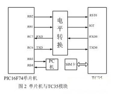
Since the TC35 data interface operates at the CMOS level, and the PIC16F74 operates at the TTL level, the operating voltage range is generally wider than the TC35, so a level shifting circuit should be added between the microcontroller and the TC35. The MCU performs data communication through the asynchronous serial interface RC6, RC7 and TC35. The communication rate is 9600kbit/s, adopting 8-bit asynchronous communication mode, 1 start bit, 8 data bits and 1 stop bit.
The MCU uses the normal IO to communicate with the serial port of the PC. The microcontroller needs to generate serial timing itself in the communication program.
3, software design
System software includes microcontroller programs and PC programs. The program of the PC is mainly to read and write the serial port of the computer, which is not detailed in this paper. The program of the single chip mainly includes the initialization, the processing of the alarm signal by the single chip microcomputer, the communication between the single chip and the PC, and the processing of the anti-disarming signal by the single chip microcomputer. The flow chart of the microcontroller program is shown in Figure 3. When the MCU detects that the GSM module has received the SMS, it first determines whether the password at the beginning of the SMS is correct or not. Only when the password is correct, the corresponding operation is performed, otherwise it will not be processed.

3.1 Microcontroller program initialization
The initialization program mainly includes setting the register, IO, and reading the user's mobile phone number and disarming password from the EEPROM into the register of the MCU. After the initialization is completed, the MCU periodically detects whether there is an alarm signal, whether it is connected to the PC, and whether the GSM module receives the short message.
The user's mobile phone number and disarming password are stored in the EEPROM to prevent the loss of important information caused by the system being powered off. The information is read into the register of the microcontroller during initialization, which saves the processing time of the microcontroller.
3.2 Processing of alarm information
The one-chip computer receives the alarm signal sent by the detection circuit through the wireless receiving circuit, recognizes the alarm type through the “identity code†of the alarm, and sends the “alarm type†to the user's mobile phone through the GSM module. After the transmission is completed, the MCU reads the alarm time from the real-time clock chip and writes the "alarm type + alarm time" to the EEPROM.
The AT command can be used to complete all the processes of controlling the GSM module for SMS communication. The GSM07.05 standard AT command set issued by the European Communications Commission ETST is the command set for sending and receiving SMS supported by all GSM modules in the world. The common AT commands are shown in Table 1. .
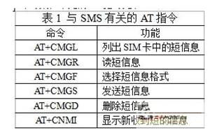
Each AT command begins with "AT+" and ends with a carriage return. The following control characters are also included in the AT command: the end character (indicated by the representation), the hexadecimal number is 0x0D, the sender character (represented by <^Z>), and the hexadecimal number is 0x1A.
Send short messages commonly used in Text and PDU (Protocol Data Unit) mode. The advantage of using Text mode to send and receive text messages is that the code is simple and easy to implement; the disadvantage is that it cannot send and receive Chinese text messages. The PDU mode not only supports Chinese text messages, but also sends English text messages. There are three modes for sending and receiving text messages in PDU mode: 7-bit, 8-bit, and UCS2 encoding. 7-bit encoding is used to send ASCII characters, 8-bit encoding is used to send data messages, UCS2 encoding is used to send Unicode characters (kanji), and encoding type is specified in PDU packets. The following is an example of the composition of the PDU encoding. For example, if you want to send the "Someone illegally open!" seven characters to the user's mobile phone 13909639342, the PDU data is: 00 01 03 0D 91 683109699343F2 32 08 0E 67094EBA975E6CD55F0095E8FF01.
The PDU data is described as follows:
(1) 00 means that the short message center number is omitted, which is determined by the SIM card;
(2) 01 indicates the file header byte;
(3) 03 indicates the type of information;
(4) 0D indicates the length of the called number;
(5) 91 indicates the type of the called number;
(6) 683109699343F2 indicates the called number, and the called number is shifted;
(7) 32 represents the protocol identifier TP-PID;
(8) 08 indicates the data encoding scheme TP-DCS, because the Unicode inner code is to be transmitted, so USC2 (16 bit) encoding is used;
(9) 0E indicates the length of the user data;
(10) 67094EBA975E6CD55F0095E8FF01 indicates the user data "People illegally open the door!".
Several issues to be aware of:
(1) The command symbols, constants, PDU packets, etc. of all AT commands are transmitted in ASCII code.
(2) After sending each instruction to the GSM module, the MCU must use the carriage return character (0DH) as the end of the command. Without this carriage return, the GSM module will not recognize this command.
(3) When the GSM module transmits a short message to the single-chip microcomputer, the content of the PDTU data packet is expressed in hexadecimal, but it is not directly transmitting the hexadecimal data to the single-chip microcomputer, but still is hexadecimal. The data is sent in ASCII encoding. Thus, the two-byte hexadecimal number becomes a 4-byte ASCII code. However, the length of the data byte in the PDU packet is still the actual byte length, not the length of the ASCII code. After receiving the data packet, the MCU must restore it to hexadecimal data.
3.3 Communication between MCU and PC
The PC can read out the alarm information stored in the EEPROM, the user's mobile phone number and the disarmed password through the single-chip microcomputer, and can modify the latter two items.
The judgment of whether the MCU communicates with the PC can be realized by hardware or by software. In order to simplify the hardware and improve the system reliability, the software is used to realize the state discrimination. After the PC is connected to the security system, when the PC sends an operation command to the MCU, the PC changes the default level state of the serial port and maintains it for a period of time. After the MCU detects the level, it enters the program for communication with the PC. . After the PC completes the transmission of the operation command, the serial port returns to the default level. After receiving the operation instruction, the MCU judges whether it is a "read" instruction or a "modify" instruction. If it is not these two instructions, it exits.
4 Conclusion
The design scheme realizes wireless communication between various parts of the system by means of the GSM network and wireless communication technology. The communication between the wireless alarm and the host is performed by means of high-frequency wireless modulation; the GSM network is used between the host and the user's mobile phone. Communication between the entire system requires no additional wiring, which saves costs and increases the reliability of communication throughout the system. The whole system is suitable for urban household use, and is also suitable for use in places such as remote areas where communication lines are inconveniently installed, and has a good application prospect.
AD8 standard floating Solar Cable is a kind of equipment used for floating photovoltaic power generation. It consists of photovoltaic cells that convert solar energy into electricity. The device is designed to float on the water, while it can be fixed to the water by a buoy and anchorage device to prevent drifting.
AD8 standard floating solar cable has the following characteristics:
1. Efficient use of solar energy: photovoltaic cells can convert solar energy into electricity to achieve efficient power generation.
2. Environmentally friendly: photovoltaic power generation does not produce pollutants and greenhouse gases and is environmentally friendly.
3. Save land resources: Floating solar cable can use the space on the water surface, saving the use of land resources.
4. Strong wind and wave resistance: floating solar cable adopts stable design, has strong wind and wave resistance, and can operate normally in bad weather conditions.
5. Easy installation and maintenance: Floating optical cables are relatively simple to install and maintain, and can be quickly deployed and adjusted.
AD8 standard floating solar cable is suitable for a variety of water environment, such as lakes, reservoirs, rivers, etc. It can be used in power stations, farmland irrigation, drinking water treatment and other fields to provide local clean energy and power supply.
AD8 Floating Solar Cable,Solar Adapter Cable,Waterproof Solar Cable,DC Cable
Suzhou Yonghao Cable Co.,Ltd. , https://www.yonghaocable.com