As the number of electronic components in automotive systems increases, the available space continues to compress, which greatly increases the density of each system. All these systems require power conversion ICs, which usually have multiple voltage rails to power each subsystem. Traditionally, linear regulators have met most of these power conversion needs because efficiency and small size are not the most important. However, as power density has increased by several orders of magnitude, and many applications need to operate in relatively high ambient temperatures, any practical heat dissipation system is too large and does not have enough space to accommodate it. Therefore, power conversion efficiency becomes critical, which leads to the replacement of linear regulators with buck switching regulators. However, emerging automotive designs require switching regulators to provide a constant output voltage regardless of whether the input is above, below, or equal to the output. The new power IC can continuously provide a good and stable output regardless of the input voltage swing, which poses new challenges for the power management IC. The power management IC must not only provide a rugged design, but also provide a solution with the highest efficiency, the lowest quiescent current, and a compact footprint.
Transient challenges of electronic systems: stop / start, cold start and load dump
In order to maximize fuel mileage while reducing carbon emissions as much as possible, some non-traditional power transmission technologies are constantly developing. Whether these new technologies use hybrid, clean diesel engines or more traditional internal combustion engine designs, it is possible to use stop-start motor designs. In all hybrid designs around the world, the stop-start motor design is almost universally adopted, and many European and Asian car manufacturers also incorporate this type of design into traditional gasoline and diesel-powered vehicles. Ford of the United States recently announced that it will use a stop-start system in many 2012 family models.
The concept of stop-start engine is very simple. When the vehicle stops, shut down the engine, and then restart the engine immediately before the vehicle accelerates. When the car is in traffic or stopped at a red light, this can reduce fuel consumption and exhaust emissions. This stop-start design can reduce fuel consumption and exhaust emissions by 5% to 10%. However, the biggest challenge for this type of design is to make the driver unaware of the entire stop-start process. To make the driver unaware of the stop-start process, two major design obstacles need to be eliminated. The first is to use the enhanced starter design to achieve a quick restart. Some car manufacturers have reduced the restart time to less than 0.5 seconds, making the stop-start process truly imperceptible. The second design challenge is to keep all electronic systems (including battery-powered air conditioners) running normally while the engine is off, while maintaining sufficient power reserves to quickly restart the engine during acceleration.
In order to incorporate the stop-start function, the design of the traditional power system must be modified. In other words, the alternator may also double as an enhanced motor starter to ensure a quick restart. In addition, a stop-start electronic control unit (ECU) must be added to control when and how the engine starts and stops. When the engine / alternator is turned off, the battery must be able to power the vehicle's various lights, environmental controls, and other electronic systems. In addition, when the engine is needed again, the battery must be able to power the starter. This extreme battery loading operation introduces another design challenge, this time an electrical challenge. Restarting the engine requires drawing a lot of current, which in turn may temporarily lower the battery voltage to 4V, which is similar to the voltage shown in Figure 1. The curve is very similar. The challenge for the electronic system is that when the battery bus voltage is briefly lower than the required output voltage, then when the charger returns to a stable state, and the battery bus voltage returns to the nominal 13.8V voltage, it is necessary to provide a good and stable 5V (or Higher) voltage.
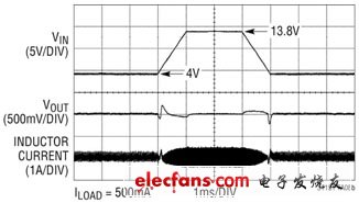
Figure 1: Transient voltage during stop-start and cold start
"Cold car start" is a situation where the car engine starts after a period of cold or freezing temperature. At this time, the oil becomes very viscous, requiring the motor starter to provide more torque, this time drawing more current from the battery. When this kind of high current load is ignited, the battery / main bus voltage may be pulled down to 4.0V, after which the battery bus voltage generally returns to the nominal 13.8V. The electrical performance of the automotive power bus looks very similar to the stop-start system shown in Figure 1, but their reasons are very different. Crucially, when a cold vehicle starts, applications such as engine control, driving safety, and navigation systems need a good and stable output voltage (usually 5V) to run continuously when the vehicle starts.
"Load dump" refers to the situation when the battery cable is disconnected while the alternator is still charging the battery. When the battery cable is not firmly connected and the car is running, or when the battery cable is broken and the car is running, a "load dump" situation may occur. This sudden accidental disconnection of the battery cable may produce transient voltage spikes of up to 60V as the alternator attempts to fully charge the non-existent battery. Transient voltage suppressors on alternators usually clamp the bus voltage between 30V and 34V and absorb most of the surge. However, the DC / DC converter downstream of the alternator suffered from transient voltage spikes of up to 36V. It is hoped that these converters can not only withstand such voltage spikes without being damaged, but also must be able to continuously regulate the output voltage during such transient events.
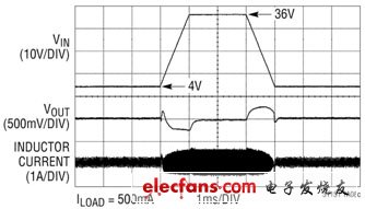
Figure 2: Voltage transient under 36V load dump
HuiZhou Superpower Technology Co.,Ltd. , https://www.spchargers.com