Abstract: The computer network control system can effectively utilize the material and intellectual resources in different places, establish an online shared resource library, and realize the computer integrated manufacturing system. This paper makes use of the advanced control technology of fieldbus, selects CAN bus as the underlying distributed control technology, designs and develops the underlying measurement and control module of CNC system based on CAN bus, which makes the information interaction of local devices more rapid.
This article refers to the address: http://
1 Introduction
A computer network system that realizes communication with various devices on the field through a bus or a microcontroller through one or more bus modes, and implements necessary control on the field device through a bus is called an underlying measurement and control communication network system, referred to as an underlying measurement and control network. . This paper is aimed at the research of numerical control system. It proposes a bottom-level measurement and control network of CNC system based on CAN bus. The field equipment is CNC equipment such as CNC machine tools.
2 The basic working principle of CAN bus
The topology of the CAN bus is a typical form of serial bus. One node in the CAN bus transmits information, and multiple nodes receive information; however, the information access mode of the CAN bus adopts a broadcast access mode. Supported in the CAN bus communication protocol is based on the way the message works. That is to say, joining or revoking the node device will not affect the work of the network, and is very suitable for the characteristics of the control system that is fast, reliable, and concise. CAN bus data communication has outstanding reliability, real-time and flexibility. CAN uses CRC check and provides corresponding error handling functions to ensure the reliability of data communication. In order to clearly explain the working principle of the remote measuring and controlling instrument of the numerical control system, we show it in the form of a structural block diagram as shown in Fig. 1. The input signal comes from the photoelectric encoder of the CNC machine motor encoder. The output signal can be servo driven or control other required signals. Here is how it works:
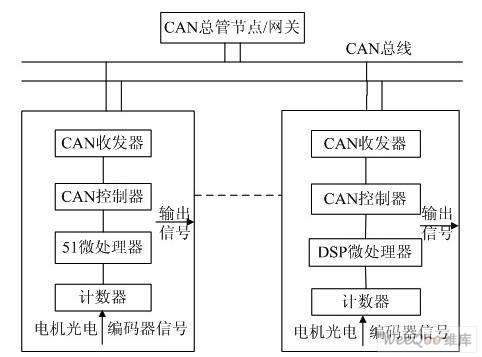
Fig.1 Working principle diagram of remote measuring and measuring instrument of CNC system based on CAN bus
The pulse output signal of the servo motor encoder enters the input end of the measuring instrument, and then is filtered by the counter, multiplied, phase-detected, counted, etc.; the microprocessor performs a relatively simple processing on the collected data, and then forwards it to the CAN controller. Inside the buffer; the mature CAN controller is further sent to the CAN transceiver (driver), and finally the CAN transceiver forwards the data to the CAN bus, the transceiver of the CAN node of the main controller, and the CAN controller; the CAN node acts as a gateway. The data of the underlying CAN node is taken out for further complex analysis processing by itself or by others. On the contrary, the above data can be transmitted to the underlying CAN node through the CAN gateway according to the same reason. In this way, the underlying and intermediate layers exchange data information. The underlying CAN node can also accept the information sent by the CAN manifold node, and transmit the command to the corresponding interface circuit and servo system through the output signal channel to control the numerical control device.
3 DSP-based CAN measurement and control instrument design and development
The microprocessor selected in this paper is TMS320LF2407 produced by TI. The system block diagram of the DSP based CAN measurement and control instrument is shown in Figure 2:
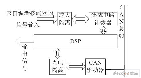
Figure 2 System block diagram of DSP based CAN measurement and control instrument
The CPU for DSP is realized by TI's 2000 series TMS320LF2407, the photoelectric isolation is realized by 6N137, and the CAN driver is realized by PCA820C250. Because the TMS320LF2407 comes with a CAN controller, there is no need to add a controller here.
3.1 measurement and control module hardware design
The intelligent nodes include signal acquisition, signal processing and signal transmission. The structure of the entire intelligent node is different depending on the peripheral interface of the selected microprocessor chip. The TMS320LF2407 selected for this system has a rich peripheral interface, so the entire intelligent node structure is simple and the system reliability is extremely strong. The intelligent node circuit with TMS320LF2407 as the core includes the following parts: power supply circuit, clock reset circuit, CAN bus interface circuit, signal conditioning part and external expansion memory circuit. The block diagram of the structure is shown in Figure 3:
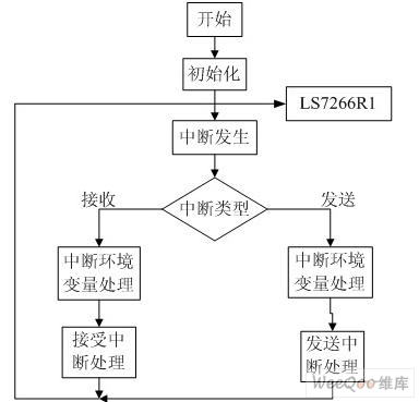
Figure 3 Overall structure of the intelligent node
Since the TMS320LF2407 has a built-in CAN module, it can be connected to the CAN bus via a CAN driver. In order to enhance the anti-jamming capability of the CAN bus node, CANTX and CANRX are not directly connected to the TXD and RXD of the CAN driver 82C250, but are electrically isolated by the high-speed optocoupler 6N137, and then connected to the 82C250. This achieves good electrical isolation between the CAN nodes on the bus, avoiding electrical interference between each other. The 3.3V.html">3.3v, 5V and 5V-CAN used in the 6N137 in this system are isolated from each other, ensuring the electrical isolation function of the optocoupler device. The interface between the 82C250 and the CAN bus also uses a certain security. And anti-interference measures. The CANC and CANL pins of the 82C250 are connected to the CAN bus through a 5 ohm resistor. The resistor acts as a current limiting device to protect the 82C250 from overcurrent. CANH and CANL are connected in parallel with the ground. Two small capacitors of 30pF can filter high frequency interference on the bus and have certain anti-electromagnetic radiation capability. In addition, a lightning protection tube is connected between the input terminals of the two CAN buses and the ground. When transient interference occurs between the input terminal and the ground, the discharge through the lightning protection tube can play a certain protective role.
3.2 Clock and Reset Circuit Design
3.2.1 Clock circuit design
This article uses a 6M crystal oscillator, the output of the crystal oscillator is directly connected to the X2 pin, and the X1 pin of the DSP is left floating. When designing the program, set the internal clock phase-locked loop of the DSP to 4 times, then the working clock of the CPU can reach 24M.
3.2.2 Reset circuit design
In the design, a simple circuit combining power-on reset and button reset is used. At the instant of power-on, the capacitor is equivalent to a short circuit. At the instant of power-on, capacitor C16 is equivalent to a short circuit. At this time, RST is low. The chip performs a reset process. After this period of time, the voltage of the capacitor reaches 2V, the reset process ends, and the chip enters the normal working area. When K1 is pressed, RST is directly connected to the ground, and the chip performs reset processing. Therefore, the operator can reset the system at any time according to his own needs.
3.3 Power circuit design
The operating voltage of TM3S20LF2407A is .33v, and the crystal oscillator, optocoupler isolation device 6N137 and CAN driver used in the design are all powered by SV. Therefore, the application system composed of TMS320LF2407A as the core is a mixed voltage system, which requires voltage. The conversion is carried out. The system uses TI's Gan 57333Q voltage conversion chip to convert the .33V voltage to the DSP.
3.4 External expansion memory circuit design
TMs320LF2407 with 4K program / data RAM, 32KFLASH program memory, the chip's own data and program memory have met the requirements of this monitoring system, so in the actual application hardware design without expanding data and program memory. However, as an initial circuit design, in order to facilitate on-line debugging, a 64K static random read/write memory is designed, which can be used together for program and data during online debugging.
3.5 Signal Conditioning Circuit Design
The signals from the sensor are voltage or current signals. At this intelligent node, an amplifying circuit and a filtering circuit are designed to amplify and filter the initial signal. In order to ensure the accuracy of the measurement, the signal with high accuracy is used to amplify the instrument amplifier AD6523. For signals with low accuracy requirements, the inexpensive LM324 is used for amplification.
The AD623 can operate in a single-supply mode. The AD623's supply voltage range is 3V-12V. The DS623 can also operate in dual-supply mode with a voltage range of ±5V to ±6V. In this intelligent node, the power supply circuit only provides 3.3V and 5V, and the operating voltage of the DSP is 3.3V, so a single power supply mode is adopted. In order to go, add a 10μf capacitor to the power supply.
4 Software design of the measuring instrument
The software of the intelligent node includes the initialization module of the system, the data acquisition module, the data processing module and the transmission module of the system. The initialization module completes the following tasks: according to the function and characteristics of the chip itself, the used registers are cleared, the program FLASH area and the data RAM area are initialized, and the interrupt port setting is prepared for the main program operation; the system power supply is also checked and protected, and the system itself is used. The built-in watchdog (WATCHDOG) monitors the hardware operation of each resource of the DSP chip. After the DSP chip can run normally, enter the main program of the data acquisition software. The channel resources, memory resources, and bus occupation resources of the data acquisition card system are allocated using the default configuration parameters. The data acquisition module starts the LS7266R1 to acquire one frame of data by the timer soft interrupt in the EMA interrupt (event management interrupt); at the same time, the data processing module The data of each channel in the previous frame has been collected. The data transmission is done through the CAN bus, so the data transmission module must complete the CAN bus communication function. In the next two sections, the design of the data acquisition, processing, and transmission modules will be described in detail based on the characteristics of the TMS320LF2407.
There are two main functions of CAN communication software: packaging the data of the intelligent node into a valid CAN information frame and sending it to the target node; receiving valid data frames from the CAN bus, and restoring the information frame to the original data for the CPU Go to the next step. The packaging and restoration of data frames are performed by the CAN controller in the DSP. In the communication software, it is only necessary to set the corresponding registers in the CAN controller. The CAN controller of the TMS320LF2407 is a complete CAN controller. The entire software process is shown in Figure 4:
Figure 4 software flow chart
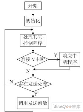
Figure 5 CAN bus communication flow chart
With the support of the CAN controller, the design of the CAN communication software becomes clear and concise. The CAN communication software design idea of ​​this system is: design the system to send data to other nodes as a function. When the system sends data, this function is called to send data to the CAN bus; the system receives data in interrupt mode, when CAN control After receiving the data, the device sends an interrupt response signal to the microcontroller, and the microcontroller reads the received data in the interrupt program. The flow chart of the whole system for CAN bus communication software management is shown in Figure 5.
The author of this article is innovative:
The bottom-level measurement and control module of the CNC system based on CAN bus designed in this paper tests the motion accuracy of CNC machine tools. The communication with various devices in the field is realized, and the necessary control of the field devices is realized through the bus, so that the information interaction of the local devices is more rapid.
Stainless Steel Industrial Pipe
Stainless Steel Industrial Pipe,Disposable SS Industrial Pipe For Laboratory,Medical Stainless Steel Industrial Pipe,High Precision Stainless Steel Industrial Pipe
ShenZhen Haofa Metal Precision Parts Technology Co., Ltd. , https://www.haofametal.com