0 Preface
The multi-band technology commonly used in the design of multi-band monopole antennas mainly includes multi-radiation branching structure, optimized feeder structure or adding input matching lumped components, optimizing the capacitive load of the radiator and ground, radiating patch slotting, adjusting the radiator Shape, the higher-order mode obtained by increasing the current density. The literature adopts the structure of multiple radiating branches, and proposes two typical multi-branch monopole antennas. The literature embeds a curved slot in the rectangular planar monopole antenna to realize the GSM / DCS / PCS tri-band antenna.
The multi-band monopole antenna proposed in this paper realizes the GSM / DCS / PCS frequency band by slotting a flat rectangular antenna. At the same time, it uses a grounded coupling radiator to effectively expand the working frequency band of the antenna and meet the TD-SCDMA standard. Because the designed antenna can be made on the same printed board as the other circuits of the mobile phone, the production price of the antenna is very low, and the antenna height is very suitable for ultra-thin mobile phones.
1 Antenna design and simulation
In traditional monopole antennas, the length of the radiation branch is about 1/4 wavelength. The radiation resistance and radiation field of a monopole antenna can be calculated using the mirror principle. Simple monopole antennas have lower radiation resistance and larger reactance. For an infinite earth whose radiation pattern is equivalent to a dipole, if the ground is gradually reduced, an ideal mirror image cannot be formed, and the current distribution on the ground will change. In modern antenna design, using electromagnetic field simulation software to simulate the antenna has become the main method of antenna design. The electromagnetic field simulation software used in this paper uses the finite difference method in the time domain to perform calculations in the time domain. Because the excitation signal can be a narrow pulse with a wide spectrum component, combined with the Fourier transform, the characteristics within the required frequency bandwidth of the calculation object can be obtained by one calculation, so it is particularly suitable for the study of broadband problems.
When the electromagnetic field is analyzed by the finite difference time domain method, the calculation space is first divided into a finite grid, each electric field component is surrounded by four magnetic field components, and each magnetic field component is also surrounded by four electric field components. The structural form of the degree equation is suitable for the difference operation of the curl equation in space, and can properly describe the propagation process of electromagnetic waves in space. Discrete Maxwell's curl equation on the above space grid and time, using the following symbols to represent the value of the arbitrary field component F at the point (x, y, z, t):
F (x, y, z, t) → F (i △ x, j △ y, k △ z, n △ t) → Fn (i, j, k)
Where: â–³ x, â–³ y, â–³ z are the space grid steps in x, y, and z directions; â–³ t is the time step; i, j, and k are integers, so a difference with second-order accuracy can be used Operation to replace differential operation.
In order to facilitate calculation and programming, the numbers of space and time are integer values, and the iterative formulas of the components of Maxwell's curl equations (1) and (2) in the passive area can be obtained from equations (3) to (8):
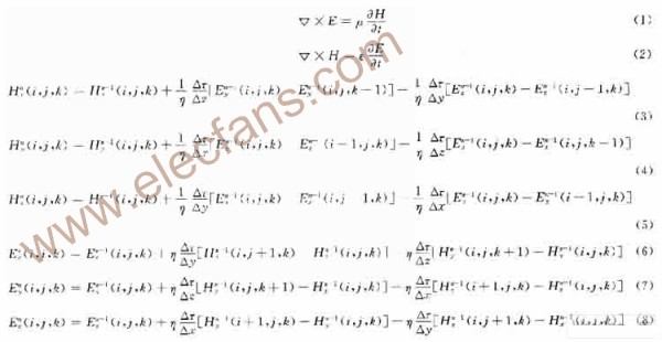
The numerical calculation space is always limited. In order to calculate the amount of electromagnetic field in a limited space, special treatment needs to be performed on the surrounding boundary of the limited space. Using PML (PeRFect Match Layer) technology in FDTD, the calculation area can be set to a vacuum, and there are scatterers and outgoing waves in the calculation area. The calculation area is surrounded by the PML absorption medium, and the PML medium is an ideal conductor.
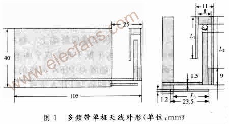
The basic multi-band monopole antenna structure is shown in Figure 1. The PCB main board is made of general-purpose FR4 material, with a board thickness of 1 mm and a size of 40 mm × 105 mm. The main radiating unit of the antenna forms two radiating branches by slotting. These two radiating branches have different lengths. By adjusting the length of the radiating branches, the antenna can obtain two resonance frequencies, corresponding to 900 MHz and 1800 MHz, respectively. The grounded radiator near the feeder is used to adjust the high-end resonance frequency, so that the operating range of the high frequency band can meet the requirements of TD-SCDMA. The final size of the antenna radiation unit is determined by the optimization of the simulation software.
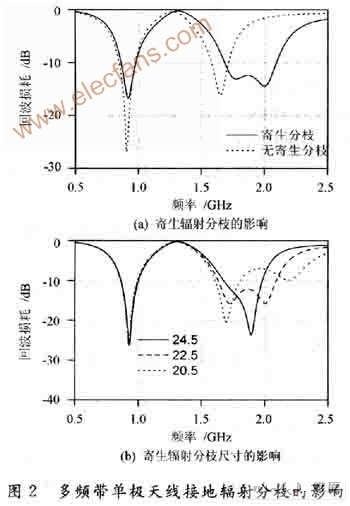
Figure 2 shows the effect of grounding parasitic radiation branches on the operating frequency band of the antenna. It can be seen from Figure 2 (a) that without ground radiation branches, the antenna can only cover GSM900 and DCS1800. By adding ground radiation branches, the antenna's operating frequency band is effectively extended. Figure 2 (b) shows the effect of the length L3 of the ground radiation branch on the high frequency band of the antenna. By adjusting its length so that it partially overlaps with the resonance frequency of the short radiation branch of the main radiator, the maximum operating frequency band can be obtained.
The effect of the structure size of the main radiating element in the antenna on the return loss of the antenna is shown in Fig. 3. Figure 3 (a) shows that the longer the length L2 of the long radiation branch, the lower the center frequency of the 900 MHz operating band, the narrower the operating bandwidth, and the lower the operating frequency of 1 800 MHz, resulting in a wider bandwidth; Figure 3 (b) shows that adjusting the length L1 of the short radiation branch has basically no effect on the 900 MHz operating band, while the lower limit of the 1 800 MHz operating band becomes lower, which widens the operating bandwidth. Through software optimization, the best structure size is obtained, which can meet the antenna design requirements.
2 Data simulation and test results
Through the above simulation analysis, the S11 parameter at the input end of the antenna is guaranteed to be less than -10 dB, and the structure size of the antenna is finally determined, where L1 = 21.3 mm, L2 = 18.75 mm, and L3 = 22 mm. According to the optimized antenna structure, a test antenna was fabricated, as shown in Figure 4. The antenna characteristics were measured using the Agilent Vector Network Analyzer E5701B (frequency range 300 kHz to 6 GHz). The actual measurement frequency range of the antenna S11 is 0.5 to 2.5 GHz. Figure 5 shows the measurement results and simulation results of antenna S11. It can be obtained from the simulation data that the operating frequency of the antenna in the low frequency band is 863 to 973 MHz, and the operating frequency of the high frequency band is 1 690 to 2 100 MHz; while the working frequency of the actually produced test antenna in the low frequency band is 888 to 990 MHz It is slightly wider than the operating frequency band of GSM900 (890 ~ 960 MHz). The operating frequency of the high frequency band is 167 ~ 2 200 MHz, covering all the operating frequency bands of DCS / PCS / TD-SCDMA (1 710 ~ 2 025 MHz). At the same time, it can be seen from the figure that the actual test results are compared with the simulated data, and the actual manufactured antenna is more consistent in GSM900; in the DCS / PCS / TD-SCDMA high frequency band, the measured data and the simulated data are slightly deviated The test antenna has a resonance point at 1 860 MHz. In addition, the resonance frequency of the parasitic radiation branch becomes relatively high.
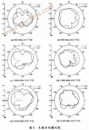
Figure 6 compares the antenna simulation pattern and the test pattern of the test antenna. It can be seen from the simulated antenna pattern that the antenna pattern is very close to the typical monopole antenna pattern. The radiation pattern in the vertical plane has better omnidirectional performance. At the same time, the increase in the operating frequency increases the lobe in the horizontal direction. , But still maintain good omnidirectional characteristics in the vertical plane. Comparing the simulated directional pattern and the actual test directional pattern, the shape of the two is very different due to the fluctuation of the test data, but the measured directional pattern is basically the same in amplitude as the simulated data.
3 Conclusion
The proposed multi-band monopole antenna uses a slotted radiating plate and coupled feed parasitic radiation branches, so that multiple resonance frequencies can be obtained in the frequency range of 888 ~ 2 200 MHz, so the design of the antenna can meet GSM900 / DCSl800 / PCSl900 and TD-SCDMA dual-mode mobile communication terminals require antennas. The test antenna made by using the optimized antenna structure after simulation can meet the design requirements and the return loss is consistent with the software simulation results.
The multi-band monopole antenna proposed in this paper has a very low height, but there is still room for narrowing the distance from the ground plane. Further improvements to shorten the distance and narrow the bandwidth can be further studied. At the same time, consider that the future communication may use the 2.3-2.4 GHz frequency band , Can continue to study a monopole antenna with a wider bandwidth.
Used in electronic products, Computers ,mobile phone
Dongguan Bofan technology Co., LTD , https://www.pengliandz.com