Design Scheme of Quantization Error of Digital Motor Control System
Quantization error generation
Digital control systems can provide designers with many advantages, such as easier implementation of advanced algorithm functions, lower cost, and more stable performance. The digital controller avoids the problems of drift, noise sensitivity and component aging in analog control. The main issue to consider when designing a digital motor control system is to choose the appropriate processor. At the same time, the processor word length is also critical. Designers need to pay attention to the problem of quantization errors caused by fixed-point number representation in fixed-point processors. These errors will reduce the performance of the control system, so that designers cannot maximize the advantages of advanced algorithms.
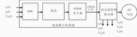
Figure 1 Universal digital motor control system
Figure 1 is a schematic diagram of the general digital motor control system. The algorithm can be implemented on the digital controller, and the control output signal generated by the digital controller can drive the motor through the inverter. Feedback signals such as current and voltage measurements are fed back to the algorithm through the ADC.
Quantification effects produce errors
The digital signal is similar to the signal it represents. Signals in the real world are continuous in amplitude and time, while digital signals have limited accuracy and are discontinuous in sampling time. That is to say, without considering the scaling, although the digital signal is different from its true analog, it is acceptable. Figure 1 shows the different quantization sources (quanTIzaTIon source) in the system. The obvious sources of quantization are: ADCs with quantization error, aperture jitter, sampling and hold error characteristics; calculation engines with truncation, rounding, overflow error characteristics, and limited quantization PWM generators with clock-driven PWM generation.
ADC quantization
For all sampled signals, the difference between the true value of the control system signal and the value represented by the ADC code is the sampling error of the system. Mainly by using a longer word length ADC to minimize sampling error (12-bit ADC is usually used in embedded controllers). When the sampling aperture is being switched, the uncertainty of the real time point will cause aperture jitter or instability. This phenomenon must be controlled by combining the sampling time point and PWM processing, especially when the minimum jitter Current sampling. During the ADC operation, the use of hardware triggers can eliminate jitter caused by software operation.
Special attention should be paid to the error when sequentially sampling multiple current measurement values. Usually, designers want to obtain the transient diagram of the motor current at a specific time in time. If a single ADC is used to sequentially sample two streams of current, a limited error will occur. Using an ADC with dual sample and hold circuits (which can sample dual channels simultaneously) can minimize such errors. Another source of error is signal interference caused by the signal loading into the input of the high-speed ADC. Careful design of the circuit will help reduce current peaks that may cause voltage interference in the inverter driver stage.
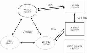
Figure 2 Overview of the selected comparison method
Quantization in algorithm calculation
The numerical representation of the algorithm is the most critical place to quantify the effect. The accuracy of the algorithm representation is determined by the word length. Control engineering research studies the influence of the choice of word length on the performance of control systems. However, there are two problems when applying theory to specific systems. In fact, for complex motor control systems such as field-oriented control (FOC) in three-phase AC induction motors, the quantization effect is difficult to obtain through analysis because the entire digital feedback system is coupled, nonlinear, complex, and multi-input / Multi-output. Second, because each system has a unique design, a single standard solution is not fully applicable to all situations. A practical and efficient method to analyze the quantization error caused by numerical representation is to study the actual digital controller and control method through simulation and experimental analysis.
The sensorless direct field-oriented control system of the three-phase AC induction motor shows the effect of quantization error. The system shown in Figure 2 has been used in simulation and real applications (with appropriate peripheral drivers). The algorithm uses 16-bit, 32-bit fixed-point and 32-bit IEEE-754 single-precision floating-point formats. All three formats use 32-bit fixed-point digital signal processing technology based on the TMS320F2812 digital signal controller and TI for 32-bit fixed-point programming IQmath library. The IQmath library allows designers to quickly and easily convert C code written in floating-point format to 32-bit fixed-point format. The code is written entirely in C and has mathematical functions provided by the IQMath library.
The simulation system can be expressed in three formats of 16-bit, 32-bit fixed-point and IEEE754 single-precision floating point, and only one of the selection results is shown here. Since the floating-point operation on the fixed-point processor is implemented by the runtime support library (rts2800_ml.lib), which is not efficient in itself, the floating-point version requires a longer sampling time to calculate all floating-point modules. Since different sampling times will affect system performance, in order to facilitate comparison, the experimental results will only focus on the fixed-point version between 16 and 32 bits.
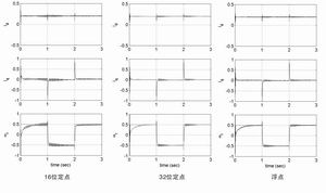
Figure 3 16-bit fixed-point, 32-bit fixed-point and floating-point simulation results
To compare the impact of the three data formats on numerical accuracy, it is necessary to monitor the estimated speed response and the corresponding d and q axis reference currents. Set all PI gains, parameters, and basic quantities to the same effective value in the simulation process of all three data formats. As can be seen from Figure 3, the performance of the 16-bit fixed-point version and the floating-point version is very different.
From the numerical performance comparison in Figure 3, it can be seen that the 16-bit fixed-point system has several false transients and ringing, while the 32-bit system does not have these phenomena. 32-bit single-precision floating-point and 32-bit fixed-point results are very similar.
In a real system, these transient phenomena can produce audible noise and vibration, which can cause many undesirable consequences. Especially unfavorable is the attenuation of the estimated speed oscillation transient and the subsequent increase that occurred at the first speed level. Figure 3 shows that this observation is very close to the edge value of the 16-bit system. On the other hand, the 32-bit fixed-point simulation system with control response has good performance.
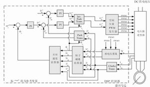
Figure 4 Realization of the motor control system
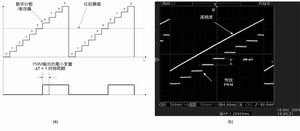
Figure 5 Standard PWM scheme diagram, and oscilloscope diagram comparison of high-resolution PWM and traditional PWM
The overflow phenomenon generally occurs when a series of addition and subtraction operations are performed through the control algorithm. Reducing the possibility of overflow in actual work through scaling algorithms can usually achieve the purpose of adjusting overflow. This can be done using additional margins labeled guard bits. Control algorithms are generally standardized in a per-unit system in order to scale all physical variables (voltage, current, torque, speed, magnetic flux, etc.). Using appropriate scaling can eliminate overflow as a source of quantization error. Examples of numerical calculations that cause quantization errors include multiplication, division, and mathematical functions for table lookups such as triangle, exponent, and square root.
As users hands or debris enter the zone 6 inches (15cm) from the infrared sensor on top of the dustbin, the lid will automatically open
Rectangular Sensor Automatic Dustbin
Rectangular Sensor Automatic Dustbin
NINGBO ZIXING ELECTRONIC CO.,LTD. , https://www.zixingautobin.com