The content of this paper is based on LabVIEW's portable automotive instrumentation test system. Therefore, we must first study the type and structure of the instrument, understand and analyze the structural principles of the vehicle's speedometer, tachometer, water temperature gauge, fuel gauge, odometer, various LED warning lights, LCD, etc. and their display principles, analysis They work with the parameters and the national standards of these tables, etc., then build the hardware platform, design the software program, and then let the software and hardware connect, set the parameters, and test.
This article is based on the LabVIEW test system, so in this paper, LabVIEW is used as the software platform of the portable vehicle instrumentation detection system. In the research, we use LabVIEW as the display of the instrument test results and the input of the instrument signal, so LabVIEW also needs this article. One of the important contents of the research.
The research content of this paper also includes the communication module in the car. In this paper, the CAN bus and the PXI board are used. Therefore, in the research, we need to study how they communicate in the car. How to connect can make us get the fastest and most accurate. data.
The main work:
This article refers to the address: http://
1. Research, research status and problems of portable automobile instrument detection systems. Analyze various automotive instruments, then analyze, process, and synthesize the data. Review relevant information, identify research topics, and conduct feasibility analysis.
2. Build a hardware and software platform related to portable vehicle instrumentation detection system based on LabVIEW.
1) Hardware platform: The hardware system of the automotive instrument test system mainly includes the industrial computer (the brain of the entire control system) and the PXI board (the PXI6528 is a static digital FO board specially designed for some slow-changing digital signals and has 24 input and 24 output, both digital signal and external output), signal junction box, data communication conversion board, CAN card, programmable network resistor, power supply and instrumentation.
2) Software platform: The instrument detection system software is designed by Nl's LabVIEW platform. This system uses LabVIEW's graphical programming language to establish a front panel man-machine interface and block diagram in a very intuitive way.
3. Repeated experiments, compared with other automotive instrument test systems, combined with the results of actual tests, repeatedly verify the correctness of the evaluation system and evaluate the effectiveness of the software.
This article uses Nl's software and hardware products and a self-developed data communication conversion card, according to various analog, digital, switch, CAN and other signals required by the portable vehicle instrument detection system.
Parameters, using Nl's PXI board and data communication conversion card to connect the hardware circuit, based on this hardware, through the Nl LabVIEW software platform to develop the entire test system, and finally proposed a complete portable vehicle instrumentation detection system theory.
Chapter II Design Plan
2.1 Feasibility analysis
2.1.1 Structure and Advantages of Virtual Instruments
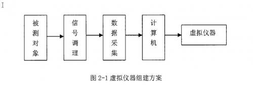
The emergence of virtual instruments is a breakthrough in the field of measuring instruments. It completely changed the traditional instrumental viewpoint, fundamentally updated the concept of measuring instruments, and brought people a new concept of instruments. Virtual instruments represent the latest direction and trends in the development of measuring instruments. It is a computer-based software instrument, with the computer as the core, the instrument function is loaded into the computer, and various instrument functions are realized through the computer. A common virtual instrument assembly scheme is shown in Figure 2-1.
The composition of the virtual instrument: the virtual instrument consists of two parts: the general instrument hardware platform (referred to as the hardware platform) and the application software:
1. General Instrument Hardware Platform
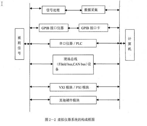
The hardware platform that constitutes the virtual instrument has two parts: one is a computer, generally a PC or a workstation, which is the core of the hardware platform; the other part is a 1/0 interface device, which mainly completes the acquisition, amplification, and mode of the input signal under test. / number conversion, etc. Different interface devices (cards) can be used depending on the actual situation. Such as data acquisition card / board (DAQ), GPIB bus instrument, VXI bus instrument module, PXI bus instrument module, serial instrument. From the hardware structure, the virtual instrument has completely deviated from the original concept of a single instrument. It does not realize the function of a certain instrument on a computer, but forms the concept of a virtual instrument system. The structure of the virtual instrument system is shown in Figure 2-2.
2. Software structure
The virtual instrument software consists of two major parts. Part of it is the application, the front panel software program that mainly implements the virtual panel function. The other part is a 10-interface instrument driver that is used to extend, drive, and communicate with specific external hardware devices. To develop virtual instruments, you must have the right software tools. There are a variety of software development tools for virtual instruments. These include textual programming languages ​​such as C, visua1C++, VISual Basie, Labwindows/CVI, and graphical programming languages ​​such as LabvIEw, AgilentvEE, and others. These development tools provide a good development environment for us to design virtual instrument applications. At present, companies such as NI have also developed software development tools for application networks for remote testing.
LabVIEW is a software product of National Instruments (IN). It is a graphical programming language and development environment. It is a recognized standard data acquisition and instrument control software. LabVIEW uses data flow programming. The flow of data between nodes in the block diagram determines the order in which programs are executed. The user interface is called the front panel in LabVIEW. Using diagrams and wires, you can programmatically control the objects on the front panel. This is the graphical source code, also known as the G (Graphies) code. LabVIEW's graphical source code is somewhat similar to a data flow diagram, so it is also called block diagram code. The LabVIEW program is called VI (Virtual Instrument), which is a virtual instrument. Because many of its interface controls and operations simulate real-world instruments, its core concept is the concept of "software is the instrument" or virtual instrument. LabV EW not only provides all the functions of hardware and data acquisition card and image acquisition card communication complying with GPIB (General-Purpose InterfaeeBus), VXI (VMEbusextensions for Instrumentation), RS (Reeonunend Standard)-232 and RS-485 protocols, but also built-in Supports library functions such as TCP/IP, ActiveX and other software standards. Its own hardware 1 / 0 function library - in addition to the plug-and-play development method, LabV EW also provides a large number of built-in hardware / 0 function library, including NI-VISA and NI-DAQmx, can support almost All bus and communication interfaces to connect more than 5,000 independent instruments and thousands of sensors, cameras and motion control drivers. LabVIEW is a true 32-bit compiler. At present, virtual instruments are widely used in various fields such as automobile, navigation, aviation, electrical and electronic, mechanical control and mechatronics, and water conservancy testing.
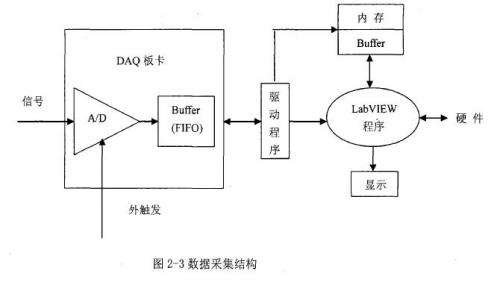
LabVIEW can be connected to any data acquisition component, including: transducers and sensors, signals, signal conditioning, data acquisition hardware, and drivers and application software. National Instruments offers the most complete data acquisition equipment for desktop, portable, embedded, and networking applications, and offers a variety of bus formats including: pCI, pexExpress, PXI, PeMeIA, uSB, eompaetFlash, Ethernet /LAN and EEE1394. Take advantage of LabVIEW's highly integrated features, including: Interactive DAQ Assistant. With the comprehensive NI-DAQmx/0 function and sensor plug-and-play TEDS technology, you can quickly develop various data acquisition systems. The data acquisition structure is shown in Figure 2-13.
Four advantages of virtual instrument technology
(1) high performance
Virtual instrument technology is developed on the basis of PC technology, so it completely "inherits" the advantages of the latest commercial technology led by off-the-shelf PC technology, including the superior processor and file 1/0, enabling you Complex analysis can be performed in real time while data is being imported into the disk at high speed. In addition, the evolving Internet and faster computer networks make virtual instrumentation a more powerful advantage.
(2) Strong scalability
These hardware and software tools make engineers and scientists no longer in the current technology. Thanks to the flexibility of the software, simply updating the computer or measuring the hardware can improve the entire system with minimal hardware investment and minimal or no software upgrades. When using the latest technology, they can be integrated into existing measurement equipment, ultimately accelerating time-to-market at a lower cost.
(3) Less development time
At both the driver and application levels, Nl's efficient software architecture combines the latest technologies in computing, instrumentation and communications. The original design of this software architecture is designed to be user-friendly, while providing flexibility and powerful features that make it easy to configure, create, publish, maintain, and modify high-performance, low-cost measurement and control solutions.
(4) Seamless integration
Virtual instrument technology is essentially an integrated software and hardware concept. As products continue to become more complex in function, engineers often need to integrate multiple measurement devices to meet the full testing needs, and connecting and integrating these different devices always takes a lot of time. The Virtual Instrument Software Platform provides a standard interface to all FO devices, helping users easily integrate multiple measurement devices into a single system, reducing task complexity.
2.1.2 Importance of automotive instrumentation detection systems
The automobile instrument is an important interface and interface for the driver and the car to exchange information, and provides the driver with the required vehicle operating parameters, faults, mileage and other information, which is an indispensable component of every automobile. Each car is equipped with a certain number of car instruments. The number and type of these electronic meters vary greatly from model to vehicle and from generation to generation. A variety of meters, indicators and alarms are indispensable parts for the driver to understand the state of the car. Automotive electronic instruments reflect the operational status of the various parts of the car and the useful information of various systems on the car. The electronic instrumentation of the car provides a guarantee for the driver to use the car correctly and drive safely. With the advancement of electronic technology, the emergence of new sensors and new electronic display devices, automotive electronic instruments have developed rapidly. The instrument panel is the main body of the installation indicator, which collects the monitoring instruments of the whole vehicle. It reveals the engine speed, oil pressure, water temperature and fuel reserve, the working state of the lights and generators, the current speed and mileage of the vehicle, etc. . Some dashboards also display information such as shift gears, clocks, ambient temperature inside and outside the vehicle, road tilt and ground height. Since the automobile instrument plays such an important role in the safe driving of our car, we should pay more attention to the detection system of the automobile instrument. Only the improvement of the detection system can improve the accuracy of the instrument and the quality of the instrument. This shows the importance of automotive instrumentation detection systems.
Most modern cars are equipped with control components for air conditioners, audio equipment, etc. on the sub-dashboard, which makes the overall layout compact and reasonable, and also facilitates the driver's operation. Automotive electronic instrumentation will become an intelligent system that integrates the functions of sensory, identification, analysis, information base, adaptation and control, providing vehicle driving information and ensuring safe driving. Automotive electronic instruments have the ability to provide a large amount of complex information; with high precision and high reliability; with a multi-purpose function; beautiful appearance design. In addition, automotive electronic instruments can be adapted to the electronicization of various sensors or control systems, saving limited interior space and meeting the requirements of small and lightweight automotive instruments.
The instruments of different car dashboards are not the same, but the general gauges of ordinary cars include speedometers, tachometers, oil pressure gauges, water temperature gauges, fuel gauges, and charging meters. Speedometer, which indicates the speed of the car, in km/h (km/h). The speedometer actually consists of two tables, one is a speedometer and the other is an odometer. A common type is to take a signal from a range sensor mounted on the gearbox, deflecting the pointer or displaying a number by changing the pulse frequency. Another common type is to take a signal on the wheel and convert it into a CAN signal or other signal through a module (such as an ABS module) and then give it to the instrument cluster. The signal source of the odometer is the same as the signal of the speedometer. The accumulated mileage data of the electronic odometer is stored in non-volatile memory (such as EEPROM), and can also be saved in the state of no electricity. The tachometer shows that the engine rotates every minute. How many turns, the tachometer unit is 1/minX1000. The speed signal is taken from the speed sensor (generally processed by the ECU module and then given to the meter). The tachometer can intuitively display the engine's speed under various working conditions. The driver can know the engine's running condition at any time, cooperate with the gearbox position and throttle position to maintain the best working condition, reduce fuel consumption and extend engine life. It is good; the fuel gauge is the amount of oil in the tank, the unit is L (liter). The current fuel signal of the company is the resistance signal of the fuel pump output. On the general instrument list, there is a fuel low alarm indicator, which serves as an auxiliary reminder; the water temperature gauge is a meter that displays the engine coolant temperature in °C (degrees Celsius).
On the general instrument list, there are indicators of high coolant temperature or low coolant level. When the indicator is on, it indicates that the coolant temperature is high or the coolant level is low.
High Voltage Dc Contactor,Epoxy Seal Contactor,High Voltage Contactor Relay,Dc Switching Contactor
NanJing QUANNING electric Co.,Ltd , https://www.quanningtrading.com